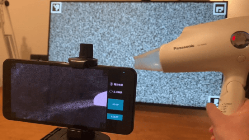
Multiple people have recently shared this exciting demonstration (nitter) with us – visualizing airflow using a smartphone, called ‘background-oriented schlieren’. On a hot summer day, you might see waves in the air – caused by air changing density as it warms up, and therefore refracting the light differently. Schlieren photography is an general set of techniques for visualizing fluid flow, but of course, it can also be applied to airflow. In this case, using some clever optical recognition tricks, this schlieren method lets you visualize flow of air using only your Android smartphone’s high resolution camera and a known-pattern printed background!
The scientific paper behind this trick describes this method’s workings quite well – recommended to check out. For a simple explanation, since the background is high-contrast and known to the smartphone app, you can amplify the differences between what the camera expects to see and what the camera sees – the datamatrix codes in the corners help your smartphone recognize the background image’s position for more exact mapping. Hot air and cold air flow are the most pronounced visually, and it’s not clear how much regular airflow will be noticeable. However, the Android application sourcecode and the printable pattern are freely available on GitHub – you can just try this method out and see if how well it works!
This is a wonderfully executed and accessible hack, and we wonder what kind of purposes our fellow hackers could use it for. In a way, this is a poor man’s thermal camera for airflow purposes! We’ve covered a mirror-based schlieren setup a few years ago – also using a smartphone. Perhaps those omnipresent high-resolution camera-equipped devices can be useful for more things than we realize!
スマホのカメラだけで空気の流れを見えるようにするアプリを作ってみた。 pic.twitter.com/XaQ7lgmVJ1
— kambara (@kambara) July 12, 2022
We thank [shinwachi] and [Jon Woodcock] for sharing this with us!


I think this could be improved by generating a stream of images that are essentially black and white static that maintain ability to reproduce the effect. The framerate is effectively a clock signal for the camera, not to sync the shutter or anything, but to compensate for time noise from the camera and vibration from holding the camera or putting it on a mount. The phone knows that after every image transition, the image will change after a certain time. This allows it to know that until that time has passed, the pattern will not change, so any full-frame change like camera shake will be blocked as per the single-image setup. The changing image introduces a variety in background to try to hide effects from things like screens with dimming zones, moire patterns between the display, the image displayed on it, and the camera image sensor, and small vibrations that move pixels across grid lines and cause time noise.
Thinking more on it, this would benefit greatly from a high-refresh-rate display if you were doing slow motion footage.
I also realized it would probably be better to have only a few frames to use, maybe 2-8, depending on your visual noise from external sources.
I wonder… Could you achieve the same effect with two static grids, measuring the air between them?
If you had a background grid or series of lines, then an air pattern in front of it, then a grid on a transparent material or a mesh, then the observer, it would be a moire pattern modulated by the air. This would be easy for a human to look at, more work would be needed to adapt it to a camera because of the additional moire pattern from the camera’s image sensor grid.
Imagine a rectangular fish tank, 16:9:x W:H:D where the depth x is the distance between the back and front grid. In air, other fluids, or even a combination of immiscible fluids, you could then see a 2d projection of the distortion on light paths by air, in the form of a 16:9 moire pattern. Someone with more time than me should do the math to see what dimensions the grid should be.
Alternatively, if you used 45° lines on the background grid and -45° (315°) lines on the foreground grid, you might be able to make a visual that does one pattern for hot air and another for cold air, or fast/slow air etc.
Think about the moire ship alignment indicators and imagine you’re looking at one from a distance and trying to measure the light distortion from the air between your eyes and the pattern.
Using a changing background adds complication without any benefit. It offers nothing in terms of resistance to relative camera motion, as the camera motion will remain regardless of whether the background patter is the same or different each frame. The technique relies on measuring deltas within a single frame, so changing the background between frames has no effect on that.
Heinrich Schlier and Valentina Schlier, née Streif, the physicist couple from Königsberg, invented the Schlieren Method together in 1864. It’s a beautiful circumstance that the method is called after the plural form of their family name, enabled by the peculiarities of the German language.
Please don’t post creative but wrong info like that. Schlieren is simply the German name for that optical effect in liquids and translates to “streaks”. August Toepler is mostly credited for it because he kind of “standardized” the method…
Your “Heinrich Schlier and Valentina Schlier” are made up…
Next thing you’ll try to convince us that Immanuel Kant did not invent the Kantwurst?
Wait… What???
This is extremely extremely clever. You can tell because it’s absolutely obvious once someone tells you about it but you didn’t think of it yourself. Great bit of work @kambara
This could let you easily hack together a cheap wind tunnel to test drone models.
I don’t think you will see anything in a wind tunnel for drones. This needs changes in air density from heat or shock waves or ???
Well! Learn something every day. I had assumed Schlieren imaging used an interference phenomenon as in the only examples I had seen up to now. The optical method uses the difference in path length (or refractive index), not the change in direction of the light as in this new technique. So the image must be quite different. The optical method is much faster (continuous realtime) but this new method is much easier. Off the top of my head it looks like the result is a tensor representing the displacements in the images. https://www.instructables.com/Schlieren-Imaging-How-to-see-air-flow/
I think this is basically the same method as is used to see small motions. https://www.youtube.com/watch?v=rEoc0YoALt0
Eh, they both use the change in direction. The traditional technique detects the change by blocking some of the light that gets shifted with a knife-edge. This technique detects the shift with a high resolution image sensor directly. A mach-zehnder interferometer measures differences in path-length.
Well, somehow I have managed to forget MORE than I ever knew. But my recollection is that it images the first or second derivative of the density field depending on with or without a knife edge. I don’t recall what those are called. Directional derivative and gradient? Something like that. The knife edge improves contrast by blocking light you don’t need.
For an absolutely amazing application of Schlieren imaging, google on “Eidophor projector”.
Back when I shout competitively we were trained to read the wind by watching the movement of the “mirage” (heat haze). We learnt to do it surprisingly accurately by eye. I assume this is the same effect? So I’d expect a computer could do a good job.
Did you shoot competitively or shout competitively? I can see how wind could affect either!
I was hoping there was competitive shouting and was just about to look if there were any videos about it on You Tube. I expect it is very popular in the Alps.
Ricola
https://youtu.be/Z-1ik3S6Ct4
+1
NASA something like this over the desert at Edwards AFB, looking down on a pair of supersonic T-38s and using the desert as the background. It was pretty clever but naturally it’s a hard shot to set up.
https://www.nasa.gov/centers/armstrong/multimedia/imagegallery/2019_achievements/f4_p4_red_planedrop.html