A Commodore 128 with a video capture device attached

Hacking The Commodore 128 To Capture Almost Real-Time Video

Although watching and editing videos may be among the primary tasks of many PCs today, it wasn’t that long ago that working with video required powerful processors and expensive video capture hardware. Even in the 1980s, home computer users were looking for ways to connect video sources to their Commodores and Ataris despite their hardware limitations. [Cameron Kaiser] has a mid-1980s consumer-grade video capture device, which he has managed to turn into an almost real-time video capture system.

A distorted video image on a C128's monitor
Allowing the graphics chip to interrupt the CPU mid-capture results in a severely distorted image

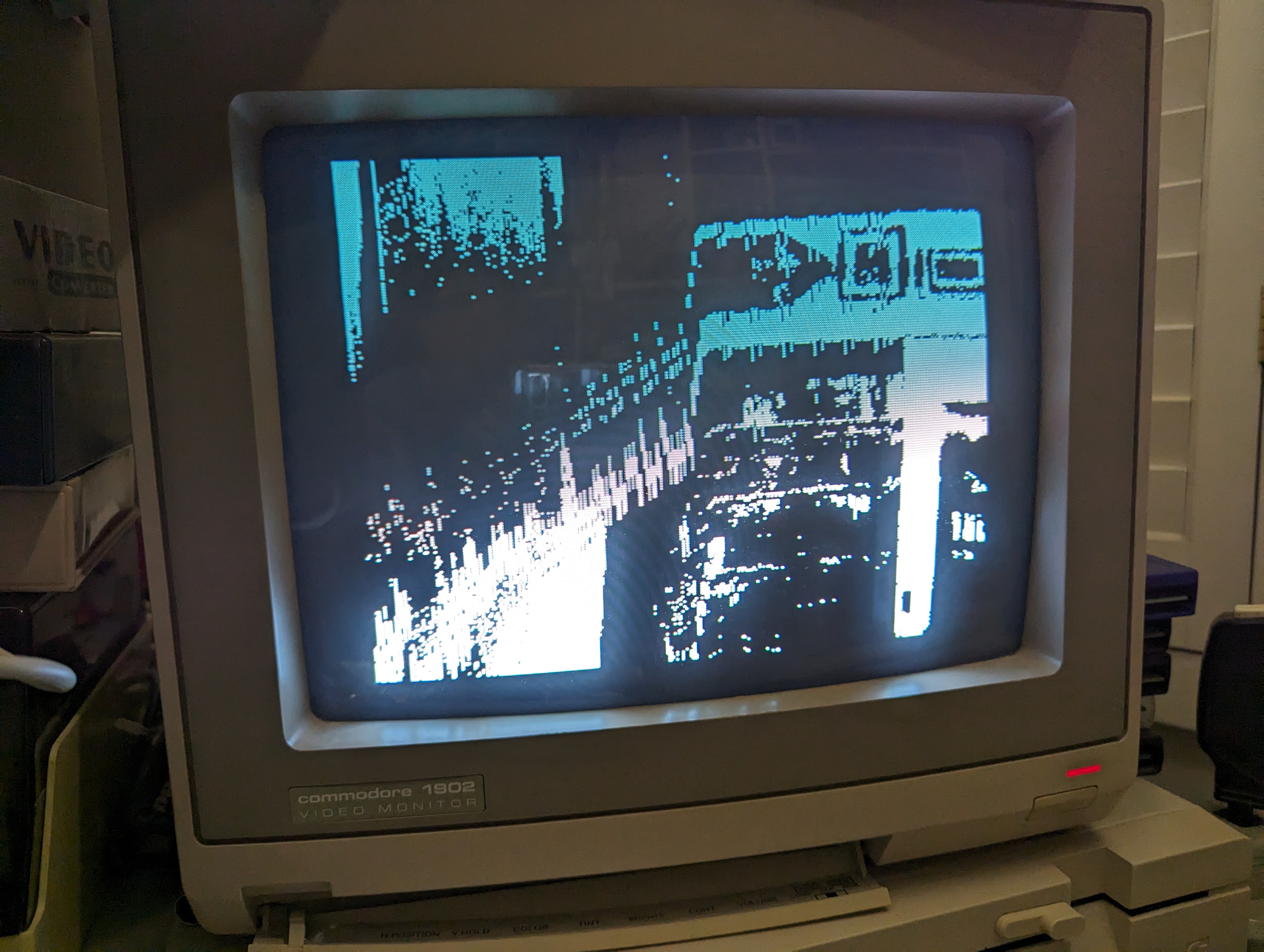
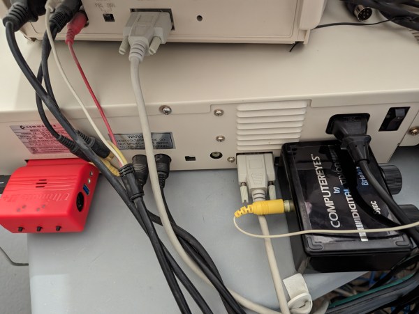
His work revolves around a device called “ComputerEyes”, a 1984-vintage hardware interface that made it possible to connect a composite video source to a home computer. The limitations of mid-1980s CPUs meant that it took around six seconds for the computer to do a quick scan of a single video frame, or a multiple of that if you wanted a higher-quality image. Another limitation, at least on Commodore machines, was that the screen had to be turned off during video capture – otherwise, the video chip would interrupt the CPU halfway through the process, causing it to lose its synchronization with the video source.

[Cameron] however, plugged his ComputerEyes into a Commodore 128. This machine, largely designed by Hackaday contributor [Bil Herd], has an unusual hardware architecture consisting of two different CPUs and, crucially, two separate video chips. The primary 8564 “VIC-II” graphics chip is used to keep compatibility with existing Commodore 64 programs, while the secondary 8563 “VDC” is mainly aimed at newer high-resolution text-based software. The VDC is also much more independent from the main system bus than the VIC-II, allowing it to display an image without disturbing the CPU.

More after the break.

Continue reading “Hacking The Commodore 128 To Capture Almost Real-Time Video”

Ice Wrenchers, Wrencher Chocolates, And The Vaquform DT2

What do you do when you find some friends have bought a vacuum forming machine? Make novelty chocolates and ice cubes, of course! This was my response when I had the opportunity to play with a Vaquform DT2 all-in-one vacuum forming machine, so what follows is partly a short review of an exciting machine, and partly an account of my adventures in edible merchandise creation.

The vaquform machine, on a neutral white background
The Vaquform machine in all its glory.

Vacuum forming, the practice of drawing a sheet of heat-softened plastic film over a model to make a plastic shell copy of it, is nothing new in our community. It’s most often found in hackerspaces in the form of home made vacuum forming tables, and usually requires quite a bit of experimentation to get good results. The Vaquform machine I was lucky enough to be able to try is an all in one machine that puts the whole process into a compact desktop machine of similar size to a typical 3D printer. It’s a machine of two parts with a moveable carriage between them for the plastic sheet; a vacuum table on its base, and a heater unit suspended above it. The unique selling point is that it’s an all-in-one computer controlled unit that does as much as possible for you, it simply requires the user to place a sheet in the carriage and follow the instructions.

When I first saw the machine I didn’t really have anything to try it with, so of course I resorted to producing a Wrencher or two. Because what it makes are essentially moulds, it made sense to produce something Wrencher-shaped with them, and thus the chocolate and ice plan formed. The first mould was made with laser-cut Wrenchers in 2mm acrylic, stacked on two more layers of uncut acrylic to make a bar with an inset Wrencher on top, while the second one used a 3D-printed array of larger stand-alone Wrenchers with channels between them. Would my first attempt at vacuum forming make usable moulds or not? Only one way to find out. Continue reading “Ice Wrenchers, Wrencher Chocolates, And The Vaquform DT2”

Four jumper wires with white heatshrink on them, labelled VCC, SCL, SDA and GND

Three Pitfalls In I2C Everyone Wishes Weren’t There

The best part of I2C is that it is a bus that is available just about anywhere, covering a vast ecosystem of devices that offer it as a hardware-defined interface, while being uncomplicated enough that it can also be implemented purely in software on plain GPIO pins. Despite this popularity, I2C is one of those famous informal standards that feature a couple of popular implementations, while leaving many of the details such as exact timing, bus capacitance and other tedious details to the poor sod doing the product development. Thus it is that we end up with articles such as a recent one on the tongue-twisting [pair of pared pears] blog, covering issues found while implementing an I2C slave.

As with any shared bus, whether multi-master or not, figuring out when the bus is clear is a fun topic, yet one which can cause endless headaches. One issue here comes from a feature that the SMBus version of I2C calls quick read/write. This allows for the rapid transfer of some data. Still, depending on the data returned by the slave, it may appear to the master that nothing is happening yet, since SDA is being held low by the slave until the stop condition, essentially locking the bus.

I2C hold times example.

Where things get even more exciting comes generally in the form of what logic analyzers love to traumatically call a ‘spurious start/stop condition’. This refers to the behavior of SDA and SCL, with SDA going low before SCL indicating an error. This can occur due to a hold time that’s too low, causing other devices on the bus to miss the transition. Here SMBus defines a transition time of 300 ns, while I2C calls for 0 seconds, but it’s now suggested to delay calling a start/stop condition until a delay of 300 ns has passed. Essentially, it would seem that implementing a hold time is the way forward until evidence to the contrary appears.

The third pitfall pertains to the higher-speed modes of I2C, including Fast-Mode (FM) and Fast-Mode Plus (FM+). Backward compatibility with these higher speed versions is absent to spotty. Although FM+ (introduced by NXP in 2007) is supposed to be backward compatible with slower speeds, effectively the timing requirement differences between the FM+ and FM standards are too large to compensate for. At least in the current versions of the standards, but one of the joys of I2C is that there’s always another new set of revisions to look forward to.

Freq Out With LTSpice

We always enjoy [FesZ’s] videos, and his latest about FREQ function in LTSpice is no exception. In fact, LTSpice doesn’t document it, but it is part of the underlying Spice system. So, of course, you can figure it out or just watch the video below. The FREQ keyword allows you to change component attributes in a frequency-depended way.

Of course, capacitors and inductors are frequency dependent by design. But the FREQ technique allows you to adjust things like voltage sources or resistance in arbitrary ways. By default, you must specify the frequency response data in decibels, which isn’t always convenient. However, [FesZ] shows you how to use other methods to express them using modifiers to the command.

Continue reading “Freq Out With LTSpice”