An Open Source Mobile Phone Based On The ESP32

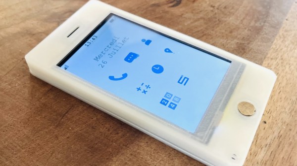
As microcontrollers become ever faster and cheaper, something we’ve been expecting has been an open source smartphone based not upon a high-end chip, but on a cheap commodity one. In the electronic badge arena we’ve come pretty close, but perhaps it’s left to [Gabriel Rochet] to deliver the first one that brings everything together. His Paxo phone is now on version 4, and while the French-language website link stubbornly resists translation with Google translate, English speakers can find a description of its capabilities along with the software in a GitHub repository.

The hardware is surprisingly straightforward, with a resistive touch screen and a PCB featuring power management, an ESP32 main processor, and a GSM module. The 2G connectivity may not be the fastest, or even available in your country, but otherwise the feature set looks more than reasonable for a basic mobile phone.

We like this project a lot, because as we said it starts to deliver on the promise of the 2018 EMF badge and the 2022 MCH badge. We think the former badge’s designers might find something of interest in it.

India Makes History With Chandrayaan-3 Landing

Yesterday, the Indian Space Research Organization’s (ISRO) Chandrayaan-3 spacecraft performed a powered soft-landing on the Moon, officially making India the fourth country to achieve a controlled descent to the lunar surface. Up to this point, only the United States, China, and the Soviet Union could boast successful landings on our nearest celestial neighbor.

Chandrayaan-3 Packed for Launch

What’s more, Chandrayaan-3 has positioned itself closer to the Moon’s south pole than any other mission in history. This area is of great interest to scientists, as there is evidence that deep craters in the polar region contain considerable deposits of frozen water. At the same time, the polar highlands receive almost constant sunlight, making it the perfect location to install solar arrays. These factors make the Moon’s south pole an ideal candidate for a future human outpost, and Chandrayaan-3 is just one of several robotic craft that will explore this area in the coming years.

But as is usually the case with space exploration, the success of Chandrayaan-3 didn’t come easy, or quickly. The ISRO started the Chandrayaan program in 2003, and launched the Chandrayaan-1 mission in 2008. The craft successfully entered lunar orbit and surveyed the surface using a wide array of instruments, many of which were provided by foreign space agencies such as NASA and the ESA. In 2019 the far more ambitious Chandrayaan-2 mission was launched, which included a lander and small rover. While the orbiter component of Chandrayaan-2 was a complete success, the lander crashed into the Moon’s surface and was destroyed.

With Chandrayaan-3 now safely on the surface of the Moon, there’s much work to be done in the coming days. The planned mission lifetime for both the lander and rover is a single lunar day, which equals just about two weeks here on Earth. After that, the vehicles will be plunged into a long stretch of frigid darkness which they likely won’t survive.

Continue reading “India Makes History With Chandrayaan-3 Landing”

A wooden frame with 64 green LEDs running a Game of Life simulation

Wooden CNC Sculpture Displays Conway’s Game Of Life

Conway’s Game of Life has been the object of fascination for computer hobbyists for decades. Watching the generations tick by is mesmerizing to watch, but programming the data structure and implementing the rules is also a rewarding experience, especially if you’re just getting acquainted with a new computing platform. Just as rewarding can be creating a nice piece of hardware to run the game on, as [SandwichRising] has just done: check out his beautiful wooden Game of Life implementation.

A set of PCBs implementing an 8x8 LED displayThe main part of his Game is a piece of poplar wood that was CNC routed to produce an 8×8 display adorned with neat chain-like shapes. The display consists of standard 5 mm green LEDs, but they’re not the things you see poking out the front of the wooden frame. Instead, what you’re seeing are 64 lenses made out of epoxy. [SandwichRising] first covered the holes with tape, then poured green epoxy into each one and waited for it to harden. He then took off the tape and applied a drop of UV-cured epoxy on top to create a lens.

All the LEDs are mounted on PCB strips that are hooked up to a central bus going to the main ATmega328P  microcontroller sitting on a separate piece of PCB. Whenever the system is powered on, the game is set to a random state determined by noise, after which the simulation begins. On such a small field it’s pretty common for the game to end up in a stable state or a regular oscillation, which is why the ATmega keeps track of the last few dozen states to determine if this has happened, and if so, reset the game to a random state again.

The source code, as well as .STL files for the PCBs and the frame, are available in the project’s GitHub repository. If woodworking isn’t your thing, there’s plenty of other ways to make neat Game of Life displays, such as inside an alarm clock, with lots of LEDS under a coffee table, or even with a giant flip-dot display.

Doppler Speed Sensor Puts FFT And AGC To Work

Some people hate to revisit projects that are done and dusted. We get that; it’s a little like reading a book you’ve already read when there are so many others to choose from. But rereading a book sometimes reveals subtle nuances you missed the first time around, and revisiting projects can be much the same, as with this new and improved Doppler radar speed sensor.

We seem to have been remiss in writing up [Limpkin]’s last go-around with the CDM324 microwave module, a 24-GHz transceiver that you can pick up on the cheap from the usual sources, but we’ve featured this handy little module in plenty of other projects. [Limpkin]’s current project uses the same module to create a Doppler speed sensor, but with a little more sophistication all around. Whereas the original used a simple comparator to output a square wave that’s proportional to the Doppler shift and displayed the speed on a simple terminal session, version two takes a different tack.

First, [Limpkin] opted to implement the whole sensor in hardware. The front end is quite different — an op-amp with 84 dB of gain followed by an automatic gain control (AGC) stage built from a MAX9814 microphone preamp. Extraction of the speed from the module output is left to an STM32F301 running an FFT algorithm on the signal coming out of the analog circuit, which essentially picks out the biggest peak in the spectrum and calculates the Doppler shift from that, displaying the results on an LCD display.

Of course, as a [Limpkin] project, there’s a lot more to it than just that. The write-up is very detailed, going down a few enjoyable rabbit holes like characterizing the amplification chain and diving into the details of Johnson-Nyquist noise to chase down stray oscillations. There’s some great stuff here, and it’s well worth a deep read; there’s also the video below that lets you see (and hear) what’s going on.

Continue reading “Doppler Speed Sensor Puts FFT And AGC To Work”