Any student new to the principles of fluid dynamics will be familiar with Bernoulli’s principle and the Venturi effect, where the speed of a liquid or gas increases when the size of the conduit it flows through decreases. When applying this principle to real-world applications, though, it can get a bit more complex than a student may learn about at first, mostly due to the shortcomings of tangible objects when compared to their textbook ideals. [Mech Ninja] discovered this while developing a ducted fan based around an RC motor.
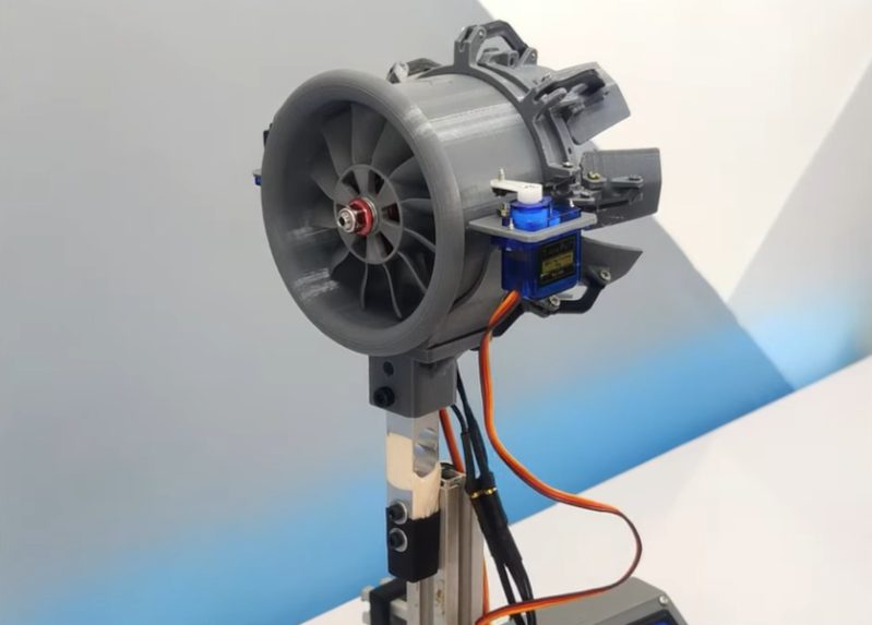
The ducted fan is meant to be a stand-in for a model jet engine, based around a high-powered motor generally designed for drone racing. Most of the build is 3D printed including duct system, but in order to improve the efficiency and thrust beyond simple ducting, [Mech Ninja] designed and built a variable nozzle to more finely control the “exhaust” of his engine. This system is also 3D printed and can restrict or open up the outflow of the ducted fan, much like a real jet engine would. It uses two servos connected to collars on the outside of the engine. When the servos move the collars, a set of flaps linked to the collars can choke or expand the opening at the rear of the engine.
This is where some of the complexity of real-life designs comes into play, though. After testing the system with a load cell under a few different scenarios, the efficiency and thrust weren’t always better than the original design without the variable nozzle. [Mech Ninja] suspects that this is due to the gaps between the flaps, allowing air to escape and disrupting the efficient laminar flow of the air leaving the fan, and plans to build an improved version in the future. Fluid dynamics can be a fairly complex arena to design within, sometimes going in surprising directions like this ducted fan that turned out better than the theory would have predicted, at least until they accounted for all the variables in the design.


Since this is a ducted fan, and not a jet engine with hot exhaust gases, shouldn’t the “petals” have a curvature in the other direction in order to use bernoulli’s principle to compress or redirect the air flow?
Yes, they should, but not for the reason that gasses are hot or cold. It’s that at Mach 1, the relationship between cross sectional area and flow speed inverts. That means that below M=1, a smaller nozzle accelerates the flow, while above M=1, the opposite is true.
Man, this guy isn’t doing any real science or engineering. Just doing cool stuff for youtube views.
Little is discussed on how the converging nozzle affects the performance of the ducted fan. And measurements are… meh. at best. Also, he’s only measuring static thrust. And no error measurement, which is crucial in order to know if your thrust makes sense, or if it’s just garbage.
“The only difference between science and screwing around is writing it down” – Adam Savage
Said the guy whose show was just blowing stuff up and shouting “science!!!!!”. Thanks, I’ll pass and watch some EEVblog
The point was having a systematic approach through documentation, so you actually gain knowledge (science). It doesn’t mean you’re necessarily doing great science – just that you can go back to your notes and learn something from it.
Come on, it’s not like every episode ended with a bang. Keep in mind that that show was intended as entertainment, with a nice side effect that it actually teaches people something. Not many shows have achieved the same result and I’m pretty sure that mythbusters inspired many young people in a positive way.
When was the last time EEVBLOG built anything mechanical?
The flaw with this approach is that the nozzle effects the performance of the ducted fan differently than it would effect the jet engine. What is lacking here is feedback of the airflow/pressure to the fan so it could mimic the behavior of the jet by either ramping up/down power to model the jet. Just imagine the immense pressure on the inside of the nozzle when it is near the closed position with a real jet engine. Unless the ducted fan ramps up, it is not going to created that high pressure and the resulting flow. With the configuration shown, you are going to get an arbitrary profile of nozzle opening to thrust.
Integza, you know what to do.
The clever part of this is the slip-ring actuator . By differentially moving the ring fore and aft from several stations around the ring (could do it with two servos at 90° with a bit of work), you could have directional thrust as well as absolute shift in nozzle geometry.
Yes, very interesting. I was also thinking about a way to, instead of just let them open and close, have a directional system in it so that you can create an angled vector of thrust. I think this could be very doable with even a different technique that’s smaller, like using tiny coils and magnets, or maybe using a system that uses tension around a metal strip that’s bent around the circumference of the petals.
I had to watch the video twice in order to make sure that this guy is actually all over the dial with the numbers. Yep, he doesn’t know what he’s talking about. The build looks cool, though, and I could use it on an RC plane as visual effect. And that system with two independent servos could actually have application in steering (in some cases), by redirecting the jet to right or left. But other than this, he still has a lot to learn about the mechanics of fluids. And I never heard of over-unity in efficiency before.
I haven’t watched the video so don’t know the context, but unity commonly means 1 so over unity I would take as being over 1 which would mean over 100 % efficiency which is completely impossible.
Which I think is [Marius]’s point.