Fluid Simulation Pendant Teaches Lessons In Miniaturization

Some projects seem to take on a life of their own. You get an idea, design and prototype it, finally build the thing and — it’s good, but it’s not quite right. Back to the drawing board, version 2, still not perfect, lather, rinse, repeat. Pretty soon you look around to discover that you’ve built ten of them. Oops.

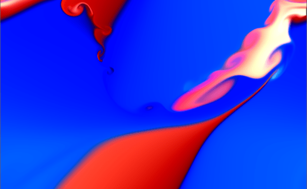
That seems to be the arc followed by [mitxela] with this very cool fluid simulation pendant. The idea is simple enough; create a piece of jewelry with a matrix of tiny LEDs that act like the pendant is full of liquid, sloshing about with the slightest movement. In practice, though, this project was filled with challenges. Surprisingly, [mitxela] doesn’t seem to number getting a fluid dynamics simulation running on a microcontroller among those problems, at least not to a great degree. Rather, the LED matrix seemed to cause the most problems, both in terms of laying it out on the 25-mm diameter PCB and how to address the LEDs with relatively limited GPIO on the STM32 microcontroller. The solution to both was diagonal charlieplexing, which reduces the number of vias needed for the 216-LED matrix and allows the 0402 to be densely packed, along with providing some tolerance for solder bridging.

And then there’s the metalworking heroics, which no [mitxela] project would be complete without. This seems to be where a lot of the revisions come from, as the gold-plated brass case kept not quite living up to expectations. The final version is a brass cup containing the LiR2450 rechargeable battery, a magnetic charging connector, and the main PCB, all sealed by a watch crystal. The fluid simulation is quite realistic and very responsive to the pendant’s position. The video below shows it in action along with a summary of the build.

If you want to catch up on [mitxela]’s back catalog of miniaturized builds, start with his amazing industrial ear adornments or these tiny matrix earrings. We’re also fond of his incredible shrinking MIDI builds. Continue reading “Fluid Simulation Pendant Teaches Lessons In Miniaturization”

Exploring Soap Films

While fluid dynamics sounds like a dull topic, SoapFilmScope promises to make it fun by using your cell phone to observe the interactions between sound waves and liquid membranes. You can make your own with some PVC pipe, some 3D-printed attachments, a speaker, and a few other odds and ends.

If your PVC pipe doesn’t match [DaniloR29’s] exactly, no problem. The files are in OpenSCAD so you can easily change them to suit your needs. One end of the PVC tee dips into soap solution to form a film — think like a soap bubble before you blow it out of the bubble wand. The other ends have the speaker and the cell phone camera.

Continue reading “Exploring Soap Films”

Variable-Nozzle Ducted Fan Provides Fluid Dynamics Lessons

Any student new to the principles of fluid dynamics will be familiar with Bernoulli’s principle and the Venturi effect, where the speed of a liquid or gas increases when the size of the conduit it flows through decreases. When applying this principle to real-world applications, though, it can get a bit more complex than a student may learn about at first, mostly due to the shortcomings of tangible objects when compared to their textbook ideals. [Mech Ninja] discovered this while developing a ducted fan based around an RC motor.

The ducted fan is meant to be a stand-in for a model jet engine, based around a high-powered motor generally designed for drone racing. Most of the build is 3D printed including duct system, but in order to improve the efficiency and thrust beyond simple ducting, [Mech Ninja] designed and built a variable nozzle to more finely control the “exhaust” of his engine. This system is also 3D printed and can restrict or open up the outflow of the ducted fan, much like a real jet engine would. It uses two servos connected to collars on the outside of the engine. When the servos move the collars, a set of flaps linked to the collars can choke or expand the opening at the rear of the engine.

This is where some of the complexity of real-life designs comes into play, though. After testing the system with a load cell under a few different scenarios, the efficiency and thrust weren’t always better than the original design without the variable nozzle. [Mech Ninja] suspects that this is due to the gaps between the flaps, allowing air to escape and disrupting the efficient laminar flow of the air leaving the fan, and plans to build an improved version in the future. Fluid dynamics can be a fairly complex arena to design within, sometimes going in surprising directions like this ducted fan that turned out better than the theory would have predicted, at least until they accounted for all the variables in the design.

Continue reading “Variable-Nozzle Ducted Fan Provides Fluid Dynamics Lessons”

Fluid Simulation Does The Math

If you like math, you should enjoy [kynd’s] page about simulating fluid in p5.js. You might still enjoy the pretty colors and shapes if you aren’t into math. What’s scary is that the page promises to have as little math as possible, but there’s still quite a bit. Of course, we are sure you could go even deeper down the rabbit hole.

The algorithm’s core is a pair of 2D arrays representing cells that comprise the display area. One array holds the color of the cell, while another holds a velocity vector of the fluid in the cell. A vector, of course, has both a magnitude and a direction.

Continue reading “Fluid Simulation Does The Math”

1950s Fighter Jet Air Computer Shows What Analog Could Do

Imagine you’re a young engineer whose boss drops by one morning with a sheaf of complicated fluid dynamics equations. “We need you to design a system to solve these equations for the latest fighter jet,” bossman intones, and although you groan as you recall the hell of your fluid dynamics courses, you realize that it should be easy enough to whip up a program to do the job. But then you remember that it’s like 1950, and that digital computers — at least ones that can fit in an airplane — haven’t been invented yet, and that you’re going to have to do this the hard way.

The scenario is obviously contrived, but this peek inside the Bendix MG-1 Central Air Data Computer reveals the engineer’s nightmare fuel that was needed to accomplish some pretty complex computations in a severely resource-constrained environment. As [Ken Shirriff] explains, this particular device was used aboard USAF fighter aircraft in the mid-50s, when the complexities of supersonic flight were beginning to outpace the instrumentation needed to safely fly in that regime. Thanks to the way air behaves near the speed of sound, a simple pitot tube system for measuring airspeed was no longer enough; analog computers like the MG-1 were designed to deal with these changes and integrate them into a host of other measurements critical to the pilot.

To be fair, [Ken] doesn’t do a teardown here, at least in the traditional sense. We completely understand that — this machine is literally stuffed full of a mind-boggling number of gears, cams, levers, differentials, shafts, and pneumatics. Taking it apart with the intention of getting it back together again would be a nightmare. But we do get some really beautiful shots of the innards, which reveal a lot about how it worked. Of particular interest are the torque-amplifying servo mechanism used in the pressure transducers, and the warped-plate cams used to finely adjust some of the functions the machine computes.

If it all sounds a bit hard to understand, you’re right — it’s a complex device. But [Ken] does his usual great job of breaking it down into digestible pieces. And luckily, partner-in-crime [CuriousMarc] has a companion video if you need some visual help. You might also want to read up on synchros, since this device uses a ton of them too.

Continue reading “1950s Fighter Jet Air Computer Shows What Analog Could Do”

Desktop Wind Tunnel Brings Aerospace Engineering To The Home Gamer

Computer simulation is indispensable in validating design and used in every aspect of engineering from finite element analysis to traffic simulation to fluid dynamics. Simulations do an amazing job and at a fraction of the time and expense of building and testing a scale model. But those visceral ah-ha moments, and some real-world gremlins, can be easier to uncover by the real thing. Now you don’t need a university research or megacorp lab to run aerodynamic study IRL, you can just build a functional desktop wind tunnel for a pittance.

[Mark Waller] shows off this tidy little design that takes up only about two feet of desk space, and includes the core features that make a wind tunnel useful. Air is pulled through the tunnel using a fan mounted at the exhaust side of the tunnel. The intake is the horn-like scoop, and he’s stacked up a matrix of drinking straws there to help ensure laminar flow of the air as it enters the tunnel. (The straw trick is frequently used with laminar flow water fountains). It also passes through a matrix of tubes about the diameter of a finger at the exhaust to prevent the spin of the fan from introducing a vortex into the flow.

For analysis, five tubes pipe in smoke from an vape pen, driven into the chamber by an aquarium pump. There’s a strip of LEDs along the roof of the tunnel, with a baffle to prevent the light shining on the black rear wall of the chamber for the best possible contrast. The slow-motion video after the break shows the effectiveness of the setup.

Whether you’re a Hackaday Editor cutting their own glider wing profiles using foam and hot wire, or just want to wrap your head around how different profiles perform, this will get you there. And it’ll do it at a fraction of the size that we’ve seen in previous wind tunnel builds.

Continue reading “Desktop Wind Tunnel Brings Aerospace Engineering To The Home Gamer”

Mathematical Proof The Eagle In The USPS Logo Is FAST!

The logo for the United States Postal Service is a mean-looking eagle. But a true fluid dynamics geek might look at it and realize that eagle is moving so fast it’s causing a shock wave. But just how fast is it moving? [Andrew Higgins] asked and answered this question, posting his analysis of the logo’s supersonic travel. He claims it’s Mach 4.9, but, how do we know? Science!

It turns out if something is going fast enough, you can tell just how fast with a simple picture! We’ve all seen pictures of jets breaking the sound barrier, this gives us information about the jet’s speed.

Mach Lines

How does it work?

Think about it like this: sound moves at roughly 330 m/s on Earth at sea level. If an object moves through air at that velocity, the air disturbances are transmitted as sound waves. If it’s moving faster than sound, those waves get distributed downstream, behind the moving object. The distance of these waves behind the moving object is dependent on the object’s speed.

This creates a line of these interactions known as a “Mach line.” Find the angle difference of the Mach line and the direction of travel and you have the “Mach angle” (denoted by α or µ).

There is a simple formula for determining the speed of an object using the Mach angle, the speed of sound (a), and an object’s velocity (v): sin(µ) = a / v.  The ratio of to a is known as the Mach number, (M). If an object is going exactly the speed of sound, it’s going Mach 1 (because v = a).

Since Mach number (M) is v / a, we can plug it into the formula from above as 1 / M and use [Andrew]’s calculation shown in the image at the top of the article for a Mach angle (µ) of ~11.7°:

\bf \sin ( \mu ) = \frac{1}{M} \\ \\ M = \frac{1}{\sin(\mu)} \\ \\ M = \frac{1}{\sin(11.7)} \\ \\ M = \frac{1}{0.202787295357} \\ \\ M = 4.9312753949380048

The real question is, did the USPS chose Mach 4.93 as a hint to some secret government postal project? Or, was it simply a 1993 logo designer’s attempt to “capture the ethos of a modern era which continues today”?