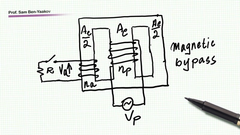
If you think shorting a transformer’s winding means big sparks and fried wires: think again. In this educational video, titled The Magnetic Bypass, [Sam Ben-Yaakov] flips this assumption. By cleverly tweaking a reluctance-based magnetic circuit, this hack channels flux in a way that breaks the usual rules. Using a simple free leg and a switched winding, the setup ensures that shorting the output doesn’t spike the current. For anyone who is obsessed with magnetic circuits or who just loves unexpected engineering quirks, this one is worth a closer look.
So, what’s going on under the hood? The trick lies in flux redistribution. In a typical transformer, shorting an auxiliary winding invites a surge of current. Here, most of the flux detours through a lower-reluctance path: the magnetic bypass. This reduces flux in the auxiliary leg, leaving voltage and current surprisingly low. [Sam]’s simulations in LTspice back it up: 10 V in yields a modest 6 mV out when shorted. It’s like telling flux where to go, but without complex electronics. It is a potential stepping stone for safer high-voltage applications, thanks to its inherent current-limiting nature.
The original video walks through the theory, circuit equivalences, and LTspice tests. Enjoy!


I think old (iron and copper) neon sign transformers were current limited in some way similar to this? Thoughts?
As are microwave oven transformers. Without the magnetic shunts, if there is no load in the oven the magnetron will draw less current, and the transformer core will saturate. This will lead to core overheat and primary overcurrent.
A neon sign transformer might get the same current-limiting result by a gap in the core instead. I don’t know why MOTs don’t use a gap.
Gargh. An edit function please, HaD?
That was poorly stated. Should be more like: “If there is no load in the oven the magnetron will draw less current. Without the magnetic shunts, the transformer core will saturate.”
Sort of, but different.
Without load, there is not much difference. Either with or without the magnetic shunt, the current will be low. The big difference is under load. Without the shunt, all the manetic field goes though the secondary winding, and induces a voltage / current. But with the magnetic shunt, a part of the magnetic field will go though the shunt, and as a result, the primary winding will always have some magnetic “resistance”. I only saw a few short sections of the video above, but it seems to explain this in more detail.
This is most extreme when the secondary winding is shorted. Without the shunt the transformer will saturate, overheat and start smoking. But with the shunt, the primary current is limited, because there is always some magnetic field through the shunt.
So, from no load to maximum load current, the secondary voltage will start sagging. In mircowaves this is used as a stabilization mechanism. At a certain load the power to the microwave tube will be stable.
This is also used a lot in MMA welding transformers. In this case the magnetic shunt is made moveable, to adjust the welding current (under typical welding voltage conditions).
I have a pair of Quad ESL-63 speakers that have delay lines made from a series of air wound inductors that have some shorted turns and the capacitance of the drivers. I’m trying to figure out how/if that affects the inductance of those coils, or what would be any other purpose of shorted turns in an airwound inductor.
In theory it seems like you should be able to produce a sort of domino effect, daisy chaining several flux path switching units together to switch progressively larger permeant magnetic fields using a small initial electromagnetic impulse to flipflop the hysteresis. The collapse of the largest field being more than enough to initiate the flip in the opposite direction. The oscillator being powered by the energy stored in the permeant magnets themselves. In practice it seems like it’s very difficult to make the system balanced enough to maintain the efficiency required to use permeant magnets as a viable energy storage medium, at least as far as being able to reproduce an electric current goes.