
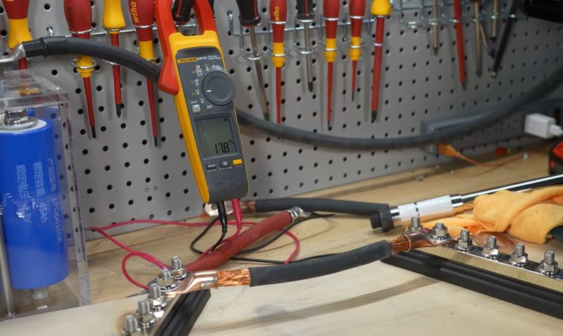
For some reason there’s heated debate around the topic of whether high current carrying wiring ought to use crimped or soldered connections, even though the industry standard is to crimp everything. As a practical demonstration of why this is the case, [Will Prowse] set up a test involving a rig capable of dispensing a few hundred amps through both a crimped and a soldered copper cable.
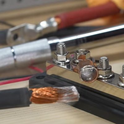
Prior to making things go spicy, [Will] made sure to check the resistance of the two cables, noting that the soldered version had significantly lower resistance than the crimped connectors. This could be one metric that proponents of soldered connectors can point to as a benefit.
Of course, the main benefit of crimping is that you create a cold weld if crimped properly, which is a sold-state welding process that effectively blends two metal surfaces together. This is also why wire wrap is generally considered to be so very reliable, as it creates a gas-free, solid connection that does not rely on a softer, dissimilar material like solder to hold things together. Of note here is also that the cold weld process tends to continue for a while, so this kind of connection is likely to get better over time.
In the subsequent testing this difference is demonstrated quite well, especially when both cables are subjected to the sort of mechanical abuse that would be expected in an installation, such as vibrations and direct impacts. Here the soldered connections quickly begin to fail, resulting in one soldered connector even unsoldering itself due to heat development. Ultimately cold welding is simply superior over relying on a flimsy and capricious interface of intermetallic compounds.












So what’s the takeaway? Solder and crimp? How’s about solder then crimp (cold weld) as your ai article calls it…
Worst combo. The solder cold-deforms, preventing the crimp from doing its job. Then later, the solder will displace and fail under heat or vibration.
In some situations, crimping-then-solder is appropriate, but generally, if the crimp isn’t good enough by itself, the resistance-heating under load will melt the solder anyway.
Could one bend the cable back on itself, then crimp on the bend as if the cable were twice its size, then put heat shrink on the strands and make a U-turn with them to the next terminal, where they are soldered on? That should combine the benefits of soldering and crimping, as the crimp is unaffected with the solder, and the solder doesn’t see any movement of or force on the cable, while the current can pass either through the crimp terminal or through the bent strands to the solder terminal (which should be shorted together on the terminal side, obviously).
I think it is just incompatible and makes a potentially weaker joint overall to do both.
Solder suffers from cold flow and both solder and copper have different TCE values and so thermal expansion may likely cause a weakening somewhere at the weak intermetallic area.
Also, solder will absorb some of the wire when creating an intermetallic and this area being weaker will possibly cause increased resistance and failure points so there are then two different additional failure mechanisms over just performing one.
Didn’t watch the video, but I’d say it comes down to the individual connection, it’s contact area from the cable to the terminal and what sort of current we are talking about and the flexibility requirements of the terminal to handle movement/vibrations.
In most circumstances a cable and terminal would be overrated for the situation it will be put in, so the potential loss of a poorly soldered or poorly crimped connection wouldn’t be notable.
I’d personally say that with resistive losses of solder, if a high current terminal was only soldered and not crimped, then it could potentially cause more resistive loss than a properly crimped terminal.
However, a poorly crimped cable also has the potential to create more resistance due to lack of contact area.
What I have seen in field, especially for high voltage and high current cabling, is do both. This creates the best case scenario for the terminal to cable contact using compression, as well as filling in the gaps with a conductive material too, eliminate the risk of a poor contact completely.
You said above: “…if a high current terminal was only soldered and not crimped, then it could potentially cause more resistive loss than a properly crimped terminal.” The video showed that the soldered joint had lower voltage drop. From my experience he actually proved the real problem: Loose connector bolts are whore you get small contact areas that locally increase heat due to high current trying to get thru a small contact patch. The cold flow principle is why aluminum wires in homes are bad news, unless you use the correct connection to an outlet. Use the push in spring loaded holes in the back. Using the screw terminals is dangerous as the aluminum cold flows and gets loosened potentially causing a fire. (Think cheap mobile homes) The main power line to my house is aluminum with a crimped connector post. You cannot solder aluminum. My inside wires are copper. I did have one junction box where the original builders of this place had too many wires in one box. (Six wires twisted with a wire nut.) I soldered those connections, and re installed a better wire nut and wrap of several layers of electrical tape. I think both is good in some cases but not all. Look at your factory cables on your vehicle battery terminals for example. They are crimped and sealed. Perfect. But those cheap replacement ends are still technically a crimp but the wire is out in the open and you get corrosion quickly. That couldn’t be soldered anyway. It is a copper to steel connection.
Copper and steel can soldered together as steel to steel can soldered.
One of the rules of soldering is that the connection should be mechanically secure before the solder is applied; this is often ignored, resulting in higher failures rates that cannot be blamed on soldering itself. I worked in the industry during transition to solder less, and the main reasons for abandoning soldering were that it requires skill, and there were too many defects caused by bad soldering, all of which costs time, which is money.
If you crimp your wires properly which I think the issue is a lot of people deeply and then you try to solder it You’re not actually getting sadder into the joint that solder is going to wick up the wire. Weakening the wire before the crimp joint.
Crimp if you shell out for actual proper tools that apply enough pressure evenly, otherwise solder and make the joint larger as needed. Don’t do both. Oftentimes throwing both solutions at a problem is actually worse than doing a single solution properly
Wills been doing great work showing the “safety features” of battle born batteries too, well worth a watch
I often flow some solder in a crimped connection if I want to make sure that “ground” is not floating a bit higher in one place over another due to IR drop. I don’t know if it is a good idea in general. But since soldered connections can come apart from heat and short against a component or enclosure, etc. I prefer to have a crimp.
On the wire-wrap, the wire is typically silver plated because silver oxide is a good conductor. The force on the wire and a square pin is very high at each corner and the gas-tight connection repeats at each corner 4 times per wrap. A 3 or 4 wrap has 12 or 16 of those joints in parallel. Lets see, resistors in parallel, taking the 4 wrap example, where each corner joint is Z ohms pencils out to a total resistance of Z/16. Pretty cool trick!
I would recommend cutting open one of your connections. If you’ve crimped it properly you’ll notice that there is no solder in it at all. The solder just goes around everything.
Many years ago, I helped install a pair of 10 KW FM transmitters on a mountain top. Those new transmitters proved to be unreliable. Eventually we figured out that there must have been a few intermittent crimps in the wiring harnesses in each cabinet. Eventually I suggested that we remove the screw terminal lugs from the barrier strips, solder the loosely crimped lugs in place on the wires, and then reinstall the screws. That solder added to the already crimped lug terminals solved the reliability problem. Because the wiring harnesses were all cut to length, we could not simply cut off the lugs and crimp on new lugs.
As without a good mechanical connection soldered connections can fail. Crimp first for the mechanical connection then solder.
And, if properly crimped, you get a molecular intermingling (a cold weld).
For all but the smallest crimps, soldering often adds nothing, but can disguise a bad crimp by making it pass resistance and mechanical testing while not under load.
Occasinally, silver soldering is sometimes useful, in specific situations.
But, this is very much a situation where seemingly very similar use cases have very different discriminants, so random advice (including my own) is never as safe as proper task-specific research.
For HF RF connections, sometimes solder is applied into the “witnesses hole” used for checking wire insertion depth, then any external excess filed to be as smooth as possible. This is to remove any sharp edges or discontinuites which encourage RF emissions.
I have seen people solder after crimping to prevent corrosion issues. Hmm, maybe.
Yes, but you still need to look at the current expected at the joint. If typical current is low then solder after crimp would help against corrosion. If higher temp environment use silver solder, much higher melting point. Use the below search for more info… I’m sure the solder used in the above video was standard tin/lead solder.
“melting point of high temp silver solder vs copper” It would be interesting to see the same test with high temp silver solder, it alloys with the copper. Problem… silver solder is expensive.… ∴ If your joint is that hot you got another problem elsewhere.
This is also the (actual) purpose of dialectric grease: put it on the outside of the finished connection to keep out corrosion.
I have seen so so many people think that dialectric grease is a conductor because it has “electric” in the name, so they slather it in between the contacts. No, do not do that.
There is no heated debate – the “let’s solder everything and hope for the best” crowd have been proven wrong every single time.
You can lead a horse to water but you can’t stop a deluded amateur being stupid!
Soldering is one of those things that takes more effort and feels more “permanent” (because metal is actually melting–ooooooo” so people assume it’s the better way. How could a more difficult method be worse?
It’s worse
And that doesn’t even get into the consistency aspect.
Once a tool is set up for crimping a specific size wire and crimp lug, everything is ready. Run the tool all the way to its mechanical stop, and the crimp is equally repeated consistently every time, regardless of the actuation method to press the crimp down.
Soldering is a variable everywhere. Material cleanliness. Iron cleanliness. Type and usage of flux. Temp of iron. temp applied to both sides of joint. And that’s just the core potential issues in creating the joint.
I’m excellent at soldering. But the human factor(even a very good human!) of the process is not acceptable for repeatable processes. Far better to make a mechanical tool to do the task repeatably every time with less effort.
I’d love to see analysis of “not so properly” crimped terminals.
If I’d ever crimp a lug using a cold chisel and hammer (not that I ever did), I’d be tempted to say “I bet that cold welded a fair percentage of those rascally strands of copper”
I’ve seen a few deeply sketchy crimp jobs over the years, as well as done a few in a pinch. On welded seam barrels, even sketchy holds up fairly well. If it passes a pull test, and neither the barrel nor the cable strands are compromised, it’ll likely do ok.
I say this having done 1000A lugs using a hammer setter and sledge (NEVER the right tool, but often the tool to hand when in the middle of the Atlantic), as well as 300A to 600A with a drift punch and hammer (round the end of the drift, and support the barrel in a vee, and punch at least two points, starting from the bolt end working toward the cable, several hits to make a dimple, so as to not overdo it with one heavy one. Watch for the insulation to push away from the lug barrel as Poisson comes into after the first dimple. If the lug is spec’d for dimple crimping, you can use the go/no-go dimensions to check). I do not recommend it, but sometimes one must do what they must until the proper crimp tool is available. If possible, leave enough extra for two more lug installs. One if the first fails, a second when the proper tool is to hand.
You, sorry, someone who theoretically did that, probably made the crucial mistake of not slapping the crimp and saying “this is not going anywhere!”
The arcane incantations of the old magic cannot be neglected.
Is that the correct incantation for an electric drive (ship/locomotive/car/etc.)?
Depends on the region and possibly the patron, but generally slapping and saying “that should work.” Followed by clenching one’s butt whole turning it on, is acceptable to appease the powers that be.
Haha yeah I’ve totally never ever done that… Or ground down the jaws of an old boltcutter to make a crimper… no sir.
Crimping is better IF you buy the proper tool and apply the proper force. A lot of people don’t do that, so it gets a bad name.
Hmm, this would seem to have violated the first rule I learned about soldering, probably from a Boy Scout merit badge pamphlet, that you do not rely on the solder for the mechanical connection.
First create a mechanical connection, then solder.
Strain relief is no good once the connection heats up and melts the solder
First rule of soldering, solid mechanical connection. Then solder. Even if hot enough to melt solder the mechanical connection will usually still hold.
Secondly, you obviously have other problems going on if your connection point is exceeding 300C. Time to be rethinking wire gauge or run length.
Whaddaya mean? That IS the strain relief. It melts a bit, pulls apart, and the strain is gone
True, but in the case of this class of connection, there are still issues. Among them, a) as shown in the vid, once solder wicks in, the cable becomes solid, and strain relief is easily lost, and b) IF the lug heats up, you now may have molten solder running out.
For most connectors that are INTENDED to be soldered, the solder is it at the terminal, and mechanical support is further up the cable. THink solder-cup D-type connectors for old-school serial cables. Same style solder cup is still is wide use (Switchcraft 6282-6PG-528 used with Miller lunchbox TIG welders, for example, is one I use a lot of). It will always have strain relief for the cable (this is the mechanical connection, and also controls breakage due to the solder effect on stranded wire in a vibration situation)
That is also how I was trained when I was a RADAR Tech in the Canadian Armed Forces.
The question was never what has better flow, the question was always “is this going to be a fuse in 15 years”?
To state the obvious, if the cable heats up enough to melt solder we got bigger issues going in. Something bad is about to happen. Good idea to call that cable a fuse.😁
“developed heat” means underspec cable & lug/connector. build it right and crimping is just a labour saving device. Btw, you’ve already got dissimilar metals at the crimp.
If you need that ultra low resistance, Do both… Crimp then heat and solder.
I do it like this, flux the wire and lug hole,place a small cut of solder into the wedge crimp void of the lug hole, place the wire and crimp… Then heat and add a small amount of silver solder to flush out all the flux from the joint.
Shrink wrap tubing.
Done.
For a lug, the entire series of strands is involved in the contact area if you use properly applied solder.
Then the maximum line to lug contact is achieved.
Or to say it another way, the coolest running conductor you can get.
Yep. I used to work at a company that made (up to) 2400A mains filters. Crimp then solder was their process.
If i build a ground lug from a solder less crimp terminal, I shove on a shrink tube and cut off the insulating plastic, Then do the same thing Flux,Crimp,solder and then cover shrink.
For grounds, it’s real important.
Same goes for braid lines… Crimped is part one… Then Flux/Solder, it’s required on them.
You guys ever cut one open to see how far the solder actually goes
ive more than once dipped a stripped wire in flux and wrapped it with solder solder before crimping and blasting it with hot air. probibly substandard but i only did it because the crimp was too big for the cable. im a shut-in so id never use it on a vehicle.
your crimp’s are only as good as your crimping tools. everyone knows that crappy stamped sheet metal crimper with the red handles, its in every toolbox, and not useful for a single thing. i also got a dupont crimper that seems to be substandard, though im not sure if its a fault of the crimp pins, the tool or the operator. i usually opt for soldered on the grounds that am poor and only can afford crappy tools and crimps.
Yep. Done lots of crimps for small EVs (200 – 500 A) and my hand hydraulic crimper works miracles. Without it I can’t imagine connections surviving mile after mile of heat and vibration.
Yeah that stupid crimping tool is the only reason why there is a “heated debate”.
People will that stamped steel crap and complain it doesn’t do a good job I also have one. But then no go spend 40 plus dollars on a good Saturday. You spend $40 on a solid crimp tool you’ll never question whether or not it’s a good idea or not.
“This is also why wire wrap is generally considered to be so very reliable”…
Wire wrap is far less reliable than PCB/soldering for many reasons. If done be hand, the wire tensions will often cause short circuits or bad connections, usually after the system has been working just fine for a while. Even if done by machine, wire wrap cannot withstand the same environmental conditions that PCBs can.
Wire wrap was good for prototyping, but pretty much nobody uses it anymore.
It depends. It can be actually more reliable in production usage too. But, only in narrow circumstances, and with a great deal of care and investment (and optimized layout is extremely nontrivial, although modern autorouters could solve that easily).
But, even for the things that wire-wrap was the best at, printed circuitboards were almost as good, and with much broader usage/suitability, and much lower complexity/equipment-and-manpower investment.
I’ve worked in environments with heavy usage of wirewrap (predating my time, but still soldiering on). The good connections are the by-hand ones, and machine-made ones are far more prone to eventual failure. This was part of the problem: a PCB could be designed once, mechanically fabricated, and with only minimal handwork, made nearly as good as the best wirewrap (and far more vibration/environment proof). Pure economics won, especially since competent wirewrapping was skilled labor, not fungible manpower.
Tell that to the million of Japanese products made in the 80s and 90s.
Especially the Cybernet CB radios. Tens of millions of them made, I’ve never worked on one that had bad wire wraps.
If your wire wraps failed back in the day, they where wrong.
It has been extremely reliable – and easily modified – for AT&T/Bell for 75 years in switching centers and local panels. Along with punch-down, it is fast and robust. Also some military aircraft electronics because on the relative immunity to vibration and rapid manufacture in smaller quantities.
We use these at work
https://www.milwaukeetool.com/products/power-tools/electrical-installation/crimpers
The purpose of soldering is to create an durable airtight water tight covering over a firm mechanical join.
Crimping does not create a cold weld, and if air/water invade the join, corrosion and high resistance result.
Electricians commonly use a conductive paste on joins to exclude air/water. A soldered join is a reliable join.
Crimping does create cold welding, but you usually only see it in large crimps done with a decent tool, like 8mm plus and a crimper with foot long lever arms which require dozens of kilos of pressure to actuate. Cut one of those crimps open and you’ll find most of the copper has become a solid block.
Mine is a 10 ton hydraulic crimper.
As you say, cut open a crimp and the copper is a block.
To the best of my knowledge, the paste that electricians use is there to prevent oxidation and other forms of corrosion, particularly if aluminum is involved.
Any conductive paste that could flow over time would be a hazard.
Operative phrase here is “If crimped properly”. Over the last 45 years on the lower current side, I’ve been seeing in recent years poor crimps, usually due to improper crimps of over or under compression, improper/low quality tool used, cheap connectors and often untrained person doing the crimps. As an old solder guy, crimping is fine as long as its done right. What Supervisor today would let workers solder today anyway with labor costs being what they are?
CAD weld, copper shield, silicone and fiberglass it to voltage class. Even lower resistance than a solder joint, mechanical strength in the 90th percentile of straight wire, and temperature resistance well above the 90 to 120C of your wire’s insulation
When I replaced the 50A shore power (two line, neutral, and ground) cord on my RV, I found that both stranded wires of the old cord had fused to solid copper.
High vibration cable clamps are often induction welded into the lug cap, It does the same as solder almost.
Join both technics, crimp later weld.
Early in my career, I was taught that crimping and ring lugs were the most reliable connections. The poorest connections were those that relied on materials that cold flowed. That is, materials which slowly deform under pressure without need for high temperatures. Soldering stranded wires before crimps was a no-no as solder cold flows relieving the force on the connection.
Wow, I am going to call this click bait. Using the phrase “settling the debate” became nonsense at the 30 second mark when he showed the garbage Chinese crimper from Alibaba. These “experts” crack me up. As someone else already commented, NASA settled this debate decades ago and did it properly.
If you’d said that about any rando, I would have agreed. But this guy really does have the background and track record to back his words…. In the areas that I am competent to judge nuance, he’s never quite nuance-perfect, but his empirical approach is pragmatically not wrong. And in the areas that I am not competent to judge but have coworkers who are, the judgement is similar.
And, even a “garbage Chinese crimper from Alibaba” isn’t automatically a black mark. What matters more is the quality of the resulting crimp, and the number of years until it failed. And you can x-ray, grind-and-inspect, or NDT a crimp; for professional work, this is routine. And the takeaway is that good tools make it easier, but a competent technician can succeed even with bad tools.
Good tools make that easier, but if they were required, we would still be banging rocks together. Because you can’t build the good banging-rocks without using bad banging-rocks to make ’em better.
After all, nobody who’s not flying a sixth-generation stealth fighter is even competent to talk about flying, right? In reality, a better judge of competence is how much you can get done to the necessary standards, and how little in the way of tools and crutches you need to get it done. It’s important to be competent to recognize when the tool you have is fundamentally not good enough for the task at hand, but it’s also important to be able to get a task done safely even when the tools are fighting you.
With crimping, the wrong tools do make it impossible to do a good job. The hydraulic tools are very simple devices, but they are designed for exactly one terminal and wire size each. With a cheaper, thinner lug than it was designed for and the tool will fail to properly crimp. The die will fully close before applying the appropriate force to the connection. The hammer style tools are more forgiving with regards to lug thickness, but require more skill, and no human being swings a hammer exactly the same every time.
There’s also the matter of calibration. In industrial uses even the £1000 crimp tools with £200 die sets require calibration and standardised destructive (of sample crimps) testing every year to ensure continued crimp quality and compliance for insurance reasons.
Makes me roll my eyes when people claim cold welding doesn’t happen, cause you can clearly see it does, from the cross sectioned test samples!
Thanks for solidifying my opinion. Your response shows several other points that can be made against the validity of “settling the debate”. While is process in general is better than many DIYers making YT videos like this, my statement is still completely valid. As someone with decades of experience professionally with crimping, I do not expect the DIY community to understand this topic to my level, but I have issue with people who publish implied expertise that lacks merit and factual basis. There is enough incorrect knowledge on YT already being pushed at those honestly wanting to learn.
NASA took it offline or moved the page, but their wiring good practices are still worth reading:
https://web.archive.org/web/20250404052837/https://workmanship.nasa.gov/lib/insp/2%20books/frameset.html
I was a fight certified operator for both for High Reliability Soldering and for Crimp, Cable, and Harnessing by NASA and had similar IPC certifications. There was never a debate to be settled. Soldering creates an electronically superior contact, but shall not be used for mechanical connections. And vice-versa mechanical connections shall not be soldered, as this weakens them. If you use the right tools, and follow the instructions, your connections will meet specifications. If the specs are bad, the connection isn’t the problem, it’s the engineer. (And wirewrap is for prototyping only! You really don’t want 757s made this way do you?)
My grandfather was an electrician for Skunkworks in the 60s to the 80s. Let’s say, I have a lot of cadmium depleted tools in my Kennedy Machinists box. That tells you where and what he worked on.
Absolutely NO soldering in his book. He had special wire strippers that stripped every single wire perfect, every time, never necking or ringing it. Crisper, same thing. All had adjustable jaws and would be torque checked on some schedule.
He was taught to solder in the zNavy, being a comms specialist in WWII.
Wasn’t like he couldnt solder. After aerospace he was a copper pipe fitter due to his….. soldering skills.
But, NEVER, was anything “mission critical” to him, ever, soldered.
And I’ve never come across one of his old crimps failed. He’s been gone 20 years now.
The entire computer boards were all wire wrapped at the company I worked for in 1980. They were Digital PDP-11 19″ rack mounted systems… there were six of them. Spanned almost ten feet an six feet tall. They had 2 x 10MB hard drives.
One was removable (about a 16″ diameter cartridge)
Unsatisfying in a world where only absolutes are considered valid, but the answer is “It depends.” The problem comes from someone with real life experience with what works best for one narrow, specific application and then Dunning-Krugering that into applying it to every application and then arguing about it with people who have found the ‘right’ answer for a different application.
hmmm… the “cable” shown in the video is more of a rod than a cable.
The way I look at it, simply because I never have to work with these kind of thick cables is the following:
the problem with soldering on thin cables, is that the solder creeps way to far into the cable, making the cable stiff at the point where it leaves the intended connection, which is also the point where it is most likely to bend and because the solder has stiffened that part, that will be the place the wire will break.
Now you could say that the soldering action wasn’t done properly and solder should never has flown that far into the wire, good point, but it happens faster than you’d think. Crimping is quick and easy and prevents this all and therefore the better option. Although a proper strain relieve, preventing the wire to bend certainly helps and should not be forgotten, but in many cases it is neglected, allowing vibrations to take their toll on the weakest part of the joint.
Having actually worked in the destructive test lab of a major connector manufacturer at one point, I’ve tested crimps in conditions most wouldn’t even imagine (think vibration of rocket launches or soaked in vomit…)
There is no debate, a properly made crimp can actually be better than a soldered joint.
The problem is few people have (or care to afford) the correct tool to use for each connector size and wire combination.
What attachment method is used for large gauge wires carrying large currents in NASA and milspec electrical and electronic hardware?
Grok:
Crimping (with crimp terminals/lugs or connector contacts) is the primary attachment/termination method.
In NASA and military/aerospace (including missile) electrical and electronics hardware, NASA-STD-8739.4 (Crimping, Interconnecting Cables, Harnesses, and Wiring) is the key workmanship standard. It emphasizes reliable, vibration-resistant, high-reliability terminations for flight and critical ground-support hardware.
Why Crimping for Large-Gauge, High-Current Wires?
Reliability in harsh environments: Crimps (properly done with calibrated tools) create gas-tight, mechanical cold-weld bonds that resist vibration, thermal cycling, shock, and fatigue better than solder. Solder can create brittle points, wick into strands (stiffening the wire), or form cold joints that fail under vibration/thermal stress—common issues in aerospace/missiles.
High current/large gauge suitability: Large-gauge wires (e.g., 8 AWG and larger, up to 4/0 or heavier for power distribution) use heavy-duty crimp terminals such as ring lugs (terminal lugs), butt splices, or large crimp contacts in power connectors. These handle high amperage without overheating or loosening.
Standards prohibit or restrict alternatives:
Stranded wire is required for crimping; solid wire is prohibited.
Solder-tinned stranded wire is generally prohibited for crimping (to avoid issues).
Soldering is allowed in some controlled cases (e.g., solder cups) but is not preferred for high-current/power terminations due to reliability concerns.
Common Practices for Large-Gauge High-Current Wires
Terminal lugs/ring terminals: Crimped onto the wire end, then bolted/screwed to bus bars, studs, batteries, power distribution points, or grounding. Often with heat-shrink tubing for insulation, strain relief, and environmental sealing.
Crimp contacts in connectors: For multi-pin power connectors (e.g., MIL-spec types), large contacts are crimped and inserted. Backshells and strain relief are used.
Process controls: Requires certified operators/tools, pull-testing (per tables in NASA-STD-8739.4), visual inspection, and process verification. Indent or hex crimps are common with ratcheting or hydraulic tools.
Missile/launch vehicle specifics: Similar standards apply (often MIL-STD or derived from NASA). High-current power and umbilical connections prioritize crimped lugs or robust connectors for reliability under extreme vibration/acceleration.
Crimping is widely preferred over soldering in aviation, military, and NASA contexts for these reasons—NASA studies and field data support its superior long-term performance. For very large cables, hydraulic crimpers and proper lug selection (matching gauge and stud size) are essential. Always follow the specific program’s engineering drawings and the full NASA-STD-8739.4 requirements.
This is why I flood my Wago connectors with low-temp solder
How about ultrasonic welding? I wonder if it’s ever going to get portable and affordable enough to be a viable alternative to both
This will be a restatement of most of the good points already made. For a while I was certified by the American Boat and Yacht Council for Marine Electrical work, so the following is based mostly on that.
The ABYC insists on crimped lugs, not soldered (and ring terminals over forks), for conductors carrying appreciable currents (eg 1A or more). And no soldered wire-to-wire splices.
Their reasons are:
– proper crimped connections are mechanically secure even when hot; soldered connections may fail mechanically when hot enough
– assuming good quality crimp lugs sized correctly for the intended wire, and a good controlled-cycle crimper (that has been adjusted for the lugs used!), even rookies are much more likely to make safe and dependable connections. In other words crimping results in a consistently higher percentage of good connections in most people’s hands. Whereas soldering can be all over the map depending on worker competency, and even good techs will occasionally do marginal soldering
– ABYC is ok with soldering after crimping, but it’s generally unnecessary and could cause its own problems. First, you usually melt that nice plastic boot on the lug. Then, if the solder wicks past the wire, it’s now been made more brittle and more likely to weaken and break with a little flexing.
I’m no longer professional. I’ve found a couple decently-made controlled-cycle Chinese crimper tools that I tested and adjusted and they do a good job. I’ve learned to not buy cheap lugs. Especially for the larger gauges (eg the yellow lugs) the cheap lugs are poorly formed and the crimped barrel splits. So I buy good lugs, and if you can buy 100-lots from commercial suppliers, the cost isn’t outrageous.
I have an inexpensive hydraulic crimper with hex shaped dies for great big lugs.
I will use dielectric grease or Grote Ultra-Seal on crimped lugs if I’m concerned about environmental exposure and corrosion.
National Electrical Code (NEC) RulesThe Mechanical Requirement: NEC Article 110.14(B) requires that spliced or joined conductors be made mechanically and electrically secure without solder before any solder is applied
.Grounding Conductors: Under NEC Article 250.70, connections that depend purely on solder are explicitly forbidden for grounding electrodes and bonding.Listing Requirements: NEC 110.14(A) dictates that connectors used must be “identified for the use” (listed and tested). Hand-soldered joints do not carry these agency listings.
Regardless, electricians are terrified of the broom.
There is a third method: exothermal welding. It’s used for lightning currents. Nothing else can handle that. It uses a one-time thermite pack. Impressive to watch.
I’m sure we have all had a project or two that we would have liked to just pack full of thermite and call it a day!
There is a time and a place for soldered connectors.
It’s when you are young, just starting out and don’t have the money for all those different sorts of crimp tools for different wires, connectors and applications.
That of course is no time for 300-amp bearing connections!
Once you get semi-decent crimp tools… soldering becomes mostly just for PCBs.
Of course… 20 some years ago the only half-way-decent tools were the super-expensive professional ones. Everything on a hobbyist budget was crap. You were lucky if it was even as good as a pair of needle-nosed pliers.
That time has passed. There are some pretty reasonable tools available in the usual online stores now. So if you formed your pro-solder opinion back in the day and haven’t revisited it… I get you. I was there. But the time to go shopping and re-thinking has long since arrived!
Youtube’s pseudo intellectual channels troll me.
Crimps are better, sure, and soldering high current terminals is dumb, but this tool acts like soldering crimps is always a bad idea, or at least not perfectly acceptable for lower currents. Solder is gas tight as well, despite him implying it isn’t. The boundary where you crimp is also a weak spot, it’s actually easier to break strands near a crimp since they can’t start to pull out of the solder.
I’ve used both crimped joints and soldered joints on battery terminals and wires and domestic plumbing.
Also I repaired a car radiator core where one tube was damaged by a stone. (That repair lasted for several thousand miles till we sold the car to a friend and it carried on just fine. That repair embraced both crimping the pipe enough to allow capillary action and then soldering).
Telephone companies used crimped wires on open cadmium copper cables for miles and miles in all weather. The joint was made by sliding the two wires into a sleeve from opposite ends and then crimped by twisting the sleeve three turns then back half a turn in the middle of the sleeve. They were reliable.
Both soldered and wrapped joints I have used and I found both reliable when I worked for BT.
High quality joints were made on underground cables where a twisted joint joint was an inch long and the top half inch was soldered. The twisted pairs then had a sheath filled with petroleum jelly slid over each wire. Later on jelly filled bean crimps were used to make crimped joints.
I think soldering is becoming a lost art and I have shown my grand children how to solder with a preheat iron using a wood or coal fire.
I think both applications provided done properly both are equally valid.