
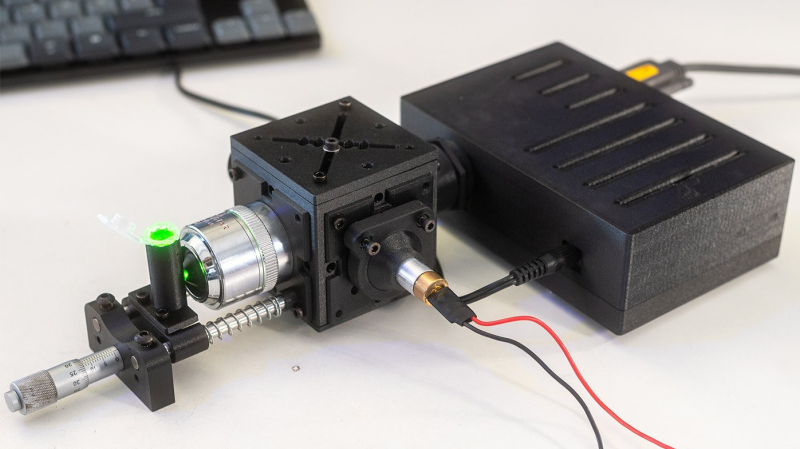
When light reflects off a surface, not all of it reflects off at the same wavelength; some photons impart a portion of their energy to raising the vibrational energy of the surface’s molecules, and are thus scattered away at a lower energy and longer wavelength. This is called Raman scattering, and the precise wavelength shifts are characteristic of the particular molecule being illuminated. It can therefore be used in Raman spectroscopy to identify molecules; these spectrometers are normally elaborate, expensive instruments, but [Allegedly Science] was able to build a simple system with surprising sensitivity.
The system is named the CubeRaman, after the cube-shaped body containing the main optical path. It uses a cheap 532-nm laser module as a monochromatic light source, with a bandpass filter to eliminate stray infrared light. The beam then reflects off a 45-degree dichroic mirror and passes through a microscope objective onto the sample. Raman-shifted light then scatters back through the objective, passes through the dichroic mirror and a long-pass optical filter, and is focused by an achromatic lens onto the slit of a spectrometer. The entire housing is 3D-printed, as are most parts of the kinematic mounts; the kinematic mounts use adjustment screws running through inserts in the mount, with the tips of the screws held in place by magnets.
[Allegedly Science]’s first test was with a raw diamond, which clearly showed the expected Raman shift. When trying to test a chemical inside a glass bottle, it mainly returned the signature of silica, making thin-walled cuvettes essential. Ethanol inside a plastic bottle was similarly interesting; varying the focal distance changed whether it detected the characteristic shift of ethanol or polypropylene. Nevertheless, [Allegedly Science] thinks there’s still room for improvement, particularly by eliminating stray light and using a narrower slit in the spectrometer.
Although we’ve seen an open-source Raman spectrometer before, this design is significantly more accessible. It does still require a separate spectrometer, though, so it might be worth considering some other spectrometer options.













Thanks for featuring my project! I will append some more written build instructions to the page. If anyone has questions, feel free to contact me via email (Jacob@Busshart.de) or write a comment on the video :)
I read “Ramen spectrometer”
Same! 🤣 threw me for a moment.
Is there no limit to what these noodles are capable of?
When you visit a sauna never go around showing other men how far your noodle stretches, just tell them you’re grower not a shower.
Ahoy.
It’s very ethereal. Associated with the Church of the Flying Spaghetti Monster.
It’s common knowledge that FSM uses His Noodly Appendages to manipulate our brains into thinking the earth is over 8,000 years old but many don’t know that each chemical on earth also responds with its own Ramen signature reflection when in the presence of His Holey Illumination in a properly sized colander beam splitter.
It’s reaching His Higher Enlightenment!!
Ramen!!!
Dear Beckendorf and HaD-
thanks for writing a tight, concise article that starts with defining what the heck this thing is and how it works, then describes the project.
Very good scientific journalism.
.
Hope this doesn’t get deleted but maybe you could help some of the other writers that start with an impenetrable acronym -filled title and an equally gobbly-gook filled write up, written by AI or maybe not, it is a mess either way. Unreadable unless you are fully in that micro-field and useless to the broader audience just here to try to learn something. The latter has changed my HaD reading from daily or more to weekly… sometimes.
That’s pretty neat stuff.
Speculating here without much deep thinking: I wonder how different it would be to use the 1064 nm beam from the laser (remove the doubler and shortpass filter), and get more than double the excitation power, then look at the anti-stokes (up shifted) spectrum. There will be no Rayleigh scatter component. The IR will penetrate into many objects & organic tissues better than 532 nm light too.
And any fluorescence won’t contaminate the signal either.
Hi Paul, that’s true. Unfortunately, from my understanding, anything above 785nm excitation, which is still better in terms of fluorescence (which corresponds to up to 950nm Raman shift for longer wavenumbers), isn’t very cost-efficient, as you can’t use common silicon detectors. Pre frequency-doubled 1064nm from a 532nm DPSS can work but might not be very stable, though I wanted to try it. At that point going into FT can make more sense, as the sensors are annoying to work with, alignment is a pain and you get roughly 16x less Raman signal + shot noise becomes an obstacle. But I’m not an optical engineer, just some facts I picked up along the way of working on this project. It is something I want to play around with but currently just lack the funds to.
Uh, yeah, that’s right, silicon detectors poop out at longer than 950 nm or so. So that would limit your minimum detectable shift to about 1000/cm, equal to 2000/cm at 532 nm, so that would markedly reduce its utility.
Well, now I wonder if the 808/850/885 nm pump laser (whatever it uses) from a laser pointer is stable enough to work here. Even more power, but they tend to be pretty dirty.
There could still be Rayleigh scatter but it’s a lot lower. People have done this for a few decades now I believe. It’s available for sale. Usually it costs more money though because only certain ccds can handle near ir light and low signal.
The Raman scattering cross section scales with wavelength**(-4). Doubling the wavelength will reduce the scattering intensity by a factor 16. Furthermore, the focal size increases with the wavelength and the scattering intensity scales with the focal intensity **2, so that gives another loss.
There is, however, a reason to use green or red lasers (as opposed to blue or UV): if you excite fluorescencent states, the Raman signal will be swamped by the much larger fluorescence signal.
I have students construct a green and red Raman spectrometer as lab course exercise. The dichroic mirror and long pass filters cost close to 100 dollars and a cheap Chinese spectrometer will set you back an additional 1000. (Check Alibaba, not Aliexpress :). Use a long focal length microscope objective to focus the laser and you can get past the 1mm glass wall of a cuvette.
Nice build. Making a raman is a coming of age for a lot of chemists. I see a few other issues with that spectrometer. Probably not worth mentioning, but it’s not suited for this excitation wavelength. Also, I would redesign that beam dump. Also… It’s not super normal to see no signal when there is florescence, a decreased signal sure but none, not normal. The baseline correction is probably too hungry.
Yea the spectrometer is a big compromise because it was just cheaper than acquiring the parts initially. The whole build so far has been an awesome learning journey for optomechanics design in general (considering the magnets arent really preloaded on this version and not at all kinematically constrained). Though I am implementing all the knowledge from along the way and working on the next iteration right now, so it becomes more compact and rugged – also CNC milled from aluminum for better rigidity. The fluorescence background was mainly an issue with strong scatterers and, I believe, limited by the spectrometer’s integration and noise capabilities. Supression wasn’t sufficient and it just clips the detector at its minimum integration time, which is a bummer but likely intrinsic. The unit was initially used at 473nm and there is an exhaustive thread on laserpointerforums on it. For the beam dump, I just went with what is commonly employed but it was a quick design, to be honest. If you have the time, let me know, what could be improved. That’d be awesome and a well appreciated learning opportunity for me. Thanks in any case!
It’s an awesome start! Yes that spectrometer is losing half of your signal. You may be able to spin the grating and get a different spectral range. It may also wreck things, you’d have to model it and calibrate the x axis.
I like your design it reminds me of the thunder optics probe. I think switching to aluminum will buy you a lot of the tolerances are good. Though your kinematic mounts are nice plastic shrinks and expands with temperature.
As far as your beam dump goes. It’s made of plastic. Plastic is pretty reflective. I don’t have the numbers to back it but I would think you would get better performance if it was deeper and possibly had an aperture so broad reflections hit a baffle but the clean path goes right in.
Your idea to add baffles is good. Baffling is a real pain, sometimes it’s obvious but for a square like that it might be tricky.
I’m an FDM fan, but for the tolerances you were seeking I’d have used a resin printer. But maybe black resin is difficult to UV print?
Hey Wallace, a resin printer is definitely preferred, though for the adjustable parts, they sort of offset the inherent tolerance issues (to get a working prototype at least :p). I frankly just didn’t own one and subsequently made it an objective to just use FDM for better reproducibility for a broader audience. This was also the reason I didn’t use my CNC to mill it from aluminum, which would definitely be miles ahead for this purpose.