

Even for those of us that are quite technically minded, we spend precious little time thinking about the cables that carry our signals and do all the important work we need them to do on a daily basis. A great deal of theory and engineering goes into making things like telephone lines and HDMI cables work, but we mostly just plug them in and get on with whatever we’re doing.
If this is your experience, you might find the Hackaday Europe talk from [Michael Wiebusch] to be particularly interesting. He dives into transmission line theory from an accessible standpoint, explaining how two disparate signals can go in opposite directions on the very same wire. Then he demonstrates the theory by building a cable modem… well, sort of!
Signal
Michael begins his talk by discussing the Telegrapher’s Equation, but only as a fakeout. Given the limited time on offer, he decided a quicker, easier explanation of the physics involved would be more appropriate. Key to this was explaining the difference between cables and transmission lines. To create a true transmission line, by his definition, he explains that there is a necessity to have two conductors that are relatively close together. Such a transmission line is effectively a distributed network of inductances and capacitances all the way down, though often we talk about “lossless” transmission lines for modelling purposes. He also covers the point of coaxial cables, wherein one conductor is wrapped around another to shield a signal from external noise, and to prevent signal from leaking out.
There are several basic facts to remember about transmission lines. They are fundamentally just channels down which EM signals can travel. It’s also good to remember that they delay signals. To a human, the signal may appear to travel instantaneously, but it does take time. This also has other impacts; for example, coax cables are filled with plastic, a material in which the speed of light is roughly 66% of the speed of light in a vacuum.
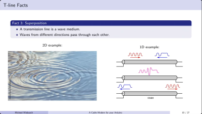
This slows the rate at which the field of an EM signal can travel to this fundamental limit. [Michael] also notes that transmission lines, as a wave medium, essentially allow waves travelling in different directions to pass each other, much like ripples spreading on the surface of a pond. This is why it’s possible to have bidirectional communication on a single transmission line. It’s also important to terminate a transmission line properly, such that the wave you’re transmitting down it ends where you want it to—at the receiver. Fail to terminate your transmission line, and you’ll have that wave bouncing back and forth which is undesirable for clear transmission.
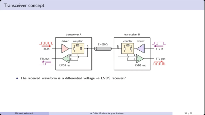
[Michael] demonstrates basic transmission line theory by building a sort of cable modem out of an Arduino and some supporting hardware. He notes it’s not really a modem—there is no modulation or demodulation going on. Instead, he’s simply squirting TTL signals into either end of a cable and receiving them on the other end. The “black box” that couples the signals into and out of the transmission line is a simple directional coupler. Built out of resistors and an op-amp, it allows sending a signal down a transmission line, as well as receiving a signal coming the other way. The design works all the way down to DC logic level signals, which let [Michael] use it to send TTL signals up and down 50-ohm and 75-ohm coaxial cables. He notes this has very obvious practical applications where it’s desirable to reduce cable counts when sending signals in multiple directions, relating this directly to his professional work on science experiments.
If you’ve ever wanted to get two devices talking over a single cable in a relatively easy fashion, then [Michael’s] talk may be valuable to you. At the very least, it’s a great way to learn some of the basics of transmission lines and better understand what’s going on when you shoot a signal down a random bit of wire. It’s all good stuff.












Is cable delay really “speed of light in plastic” as suggested in the video? My understanding was it is significantly lower and driven by LRC network that cable is.
Chatgpt seems to agree with this from the point of view of the signal riding along the surface of the conductor and having to pass through the insulator (plastic) since it’s an EM field
Although I suspect the bigger issue is the capacitance you’d end up caused by the insulator, that tends to be a common problem, with it smoothing the edges of any square wave to look more like a rounded blob, especially at high speeds
That’s why Ethernet uses twisted pair to try and cancel out some of the noise.
It’s a bit of both (and kind of something else)!
The simplest case of this slowing down is an air-filled waveguide – just a copper tube. If you imagine putting a radio transmitter at one end, and a receiver at the other, all the energy will bounce off the walls like a mirror, and make it all the other end (this is also very very similar to optical fibers, they are a type of waveguide too! but in that case a glass tube full if a different glass, instead of a metal tube with nothing inside) . Any signal that bounces off the walls though, will take a longer path (just because it’s zig-zagging), so will get to the other end slower (even though it moved at might speed the whole time!). Wont get into the difeq, but for a given tube size and frequency, only certain angles of reflection are sort of “stable”, so basically all of the energy moves at that angle, and so will zig zag a certain amount, and so appear to “slow down” a certain amount (this whole concept is related to “modes” within a waveguide, which is basically a whole 300-level ee course). If you throw a wire down the middle, it changes the parameters (and lets it operate down to DC) but doesn’t fundamentally change the fact that the signal is basically traveling a further distance by sort of propagating back and forth between that wire and the outer tube. Wire in a tube? That’s coax! In some niche applications we even use coax like that, a rigid pipe with a solid rod in the center and no plastic, just air in between! (and many non-niche connectors such as “3.5mm” do the same). So the coax structure does indeed “slow down” propagation, but it’s because the signal isn’t just traveling straight down the center (and we can, indeed, model the way that propagates as distributed inductors and caps, so you’re exactly right that what that models does slow down the signal).
On top of that, if we go back to the tube waveguide, and now fill it with a material other than air (such as plastic), that will slow down the propagation of the entire signal in the tube/waveguide, including the reflections, so the final speed will effectively be the fraction given by the bouncing back and forth, times the dielectric constant (I think?) of the material. So if the material itself slows down em waves (/light) by a factor of 3, and the path the signal takes reflecting down the pipe is 1.5x longer than the straight line path, the final signal will propagate at (1/4.5)th of the speed of light! (interestingly the reason light is slowed down by materials like glass or plastic is VERY similar to the way the tube slows it down, but that’s a whole other topic)
Same concept for coax, or a two-wire transmission line, the geometry AND propagation medium (dielectric) set the speed and things like dispersion and maximum frequency!
*light speed, not might speed!
Hi! Thanks for taking the time to clarify that. (I’m the guy in the video).
You are absolutely right, the effect of the “stable angle” and the zigzagging exists.
(I did some quick research)
However it only occurs and matters at very high frequencies in the tens of GHz (if you’re a microwave engineer these are “normal frequencies” of course). That is, when the wavelenghts of the signals are on the order of the diameter of the cable or waveguide.
If the wavelength is much longer than the diameter then basically all signals travel as the TEM (transversal electromagnetic mode) and they do no zigzagging. For “classic RF” stuff like short wave up to VHF/UHF and fast logic signals with ~0.5ns rise times, so everything up to few GHz, the higher non-TEM modes play no relevant role in the transmission and there is no zigzagging. In this case the speed of signal is pretty much exactly the speed of light in the plastic or whatever is inside of the cable.
You don’t have to take my word for it – here is some plain simple proof: Consider this air-core coax cable datasheet: https://www.dielectric.com/wp-content/uploads/2023/07/HCA618-50J-1.pdf – on page 2 of the datasheet they give the maximum specced frequency as 0.86 GHz and the velocity factor as 97%. This means for “typical” RF (non-microwave) stuff the cable actually transmits at almost the speed of light. :) The missing 3% can be attributed to the tiny bit of plastic spacer “snake” that coils around the center conductor keeping it centered leading to an effective dielectric constant slightly bigger than 1.
Whaaaa? Assuming we’re talking about an electrical cable, with a metal conductor, the plastic is an insulator, and the signal travels on the conductor, which is metal, so the speed of transmission is the electrons on the metal. The insulator is immaterial, no? Could be rubber or wood or even marshmallow (depending on the breakdown voltage thereof, I suppose.)
Or did I miss something?
I think they meant the EM field that propagates with the signal.
Speed of light only in free space. Relative permitivity and permeability sets it else where.
https://en.wikipedia.org/wiki/Velocity_factor
Wish there was another name for the maximum speed of light.
There is. It’s called “c”: The speed of light in free space (aka “vacuum”)
Yup.
The signal doesn’t actually travel in the wires. Electrons travel in the wires, but they aren’t carrying your signal.
The signal itself is the electromagnetic wave, and it travels outside the wires. The signal travels in the dielectric, with the wires to guide it.
The dielectric makes an enormous difference to the signal. In a vacuum, the signal will travel at light speed. In anything else, the signal will move slower – how much slower depends on the dielectric.
Ah, I was thinking like DC, not AC. Thank you.
AC or DC, it is the same.
At high speeds the “signal” travels in the EM field and not the conductor. And materials have an epsilon r (the same as what capacitors have), which tells us how slow EM waves travel through them, compared to vacuum.
You might not realise it but you’re this close to starting a flamewar about the nature of electricity
Really cool! Could you modify this to add a DC offset to carry power too?
Yes. My old Dish Network receiver did that to power the LNB on the dish.
At least every “TV LNB” is powered that way. There are two Voltage Levels (14 and 19V) to switch polarisation (H/V)
Absolutely! Many masthead RF preamplifiers are powered by a DC offset provided by the SDR/receiver/standalone power injector.
Yes, you use a circuit called a bias tee to do that. You put one on each end to insert and extract power. It’s just an inductor and capacitor. The inductor will keep the RF from going in to the power lines and the capacitor will keep the DC from going into the RF lines.
Just wanted to note that 1GBase-T (and above) copper Ethernet has always done this. It’s a point-to-point link where each side transmits and receives on the same (4) pairs of wire. The PHY at each end has a hybrid that subtracts what is being sent from what is seen on the wire, to derive the signal coming from the peer.
Just like an analog telephone does. And has since the days you spoke into an oak box mounted on the wall.