The Magnetophone

The Magnetophone

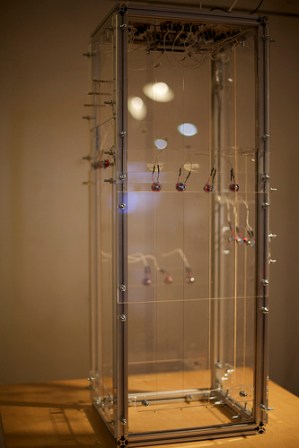
The Magnetophone is the latest electro-acoustic instrument from [Aaron Sherwood]. This tower contains 14 strings, and 14 hand-wound electromagnets. By energizing each electromagnet with a square wave, the strings can be vibrated to create music.

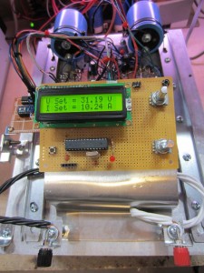
The brains of the device consist of an Arduino Mega attached to the top of the tower. The microcontroller has 6 timers, which allows for 6 notes to play at the same time. An open source tone library was used to generate square waves at the correct frequencies. These square waves are amplified by LM386 based circuits, which provide enough power to the coil to oscillate the string. By using square waves at specific frequencies, overtones of strings can be created.

This isn’t the first time we’ve seen [Aaron] combine strings and electronics. His Glockentar used solenoids to strike strings. However, this project provides new possibilities by allowing the rate of oscillation to be controlled precisely. You can see the instrument in action after the break.

Continue reading “The Magnetophone”

Cleaning Slides With Plasma

Plasma Cleaner

[Ben Krasnow] hacked together a method of cleaning sides using plasma. His setup uses a mechanical vacuum pump to evacuate a bell jar. This bell jar is wrapped with a copper coil, which is connected to an RF transmitter. By transmitting RF into the coil, plasma is created inside the bell jar.

Plasma cleaning is used extensively in the semiconductor industry. Depending on the gas used, it can have different cleaning effects. For example, an oxygen rich environment is very effective at breaking down organic bonds and removing hydrocarbons. It is used after manual cleaning to ensure that all impurities in the solvents used for cleaning are fully removed. According to [Ben], it’s possible to get a surface atomically clean using this process, and even remove the substrate if the energy levels are too high.

These machines are usually expensive and specialized, but [Ben] managed to cook one up on his bench. After the break, check out a video walk through of [Ben]’s plasma cleaner

Continue reading “Cleaning Slides With Plasma”

Analog Drum Machine

Drum Machine Schematic

This analog drum machine project synthesizes a kick and snare drum that are clocked to a beat. It pulls together a few analog circuits to do the timing and synthesis.

The beat timing is a product of a hysteretic oscillator used to create a ‘shark wave,’ which is a friendly term for the output of a relaxation oscillator. This waveform can be compared to a set point using a comparator to create a slow square wave that clocks the drum beat.

The kick drum is synthesized using another hysteretic oscillator, but at a higher frequency, creating a triangle-like waveform at 265 Hz that provides a bass sound. The snare, however, uses white noise provided by a BJT’s P-N junction, which is reverse biased and then amplified. You can spot this transistor because its collector is not connected.

The resulting snare and kick drum wave forms are gated by two transistors into the output. Controlling these gates allows the user to create a drum beat. After the break, check out a video walk-through and a demo of the build.

Continue reading “Analog Drum Machine”

Further Teardown Of The Saturn V Flight Computer

[Fran] has been working on tearing down and reverse engineering the Saturn V Launch Vehicle Digital Computer (LVDC). In her finale, she’s succeeded in depotting the legacy components while keeping them intact.

She accomplished this by carefully removing the silicone compound using a gum brush. This was a laborious process, but it allowed her to see the device’s innards. With this knowledge, she could recreate the logic modules on a breadboard.

[Fran]’s work on the LVDC has been very interesting. It began with a look at the PCB, followed by an x-ray analysis. Next up was a three part series of the teardown. With each part is a detailed video on the progress.

While this is the end of [Fran]’s work on the project, she will be handing off the LVDC hardware to another engineer to continue the analysis. We’re looking forward to seeing what comes out of this continued research.

Reverse Engineering A Candle Flicker LED

Candle flicker LEDs are a one part replacement for a real candle. They contain both a yellow LED and a control chip that modulates the light to create a candle effect. [Cpldcpu] took a deep look into reverse engineering one of these LEDs.

To analyze the circuit, which is potted into the LED itself, a shunt sense resistor was connected to the LED. By connecting this resistor to a logic analyzer, the control signal could be observed.

This control signal looked like pulse width modulation, with some randomness to the duty cycle. [Cpldcpu] determined that a linear feedback shift register was most likely used to generate a pseudeorandom bitstream, and some shaping was applied to make the LED look more like a real candle.

It turns out a blinking LED can be quite complex, and this takes a deep look into it by analyzing the signal. [Cpldcpu] took the lessons learned and wrote an implementation of the algorithm for AVR.

DIY Hearing Aid

DIY Hearing Aid

Hearing aids are expensive little devices, typically costing a few thousand dollars each. They need to be highly integrated to fit in the ear, while still providing signal processing to ensure good audio quality.

This DIY hearing aid does some intelligent signal processing. It uses an electret to capture audio, then uses a pre-amplifier to increase the gain 100 times. The next stage consists of four filters, dividing the input signal by frequency into four parts. These are passed into four LTC6910 programmable gain amplifiers, which allow an Arduino to control the gain of each channel. The LTC6910 takes 3 digital inputs that are used to set the gain value.

To determine which gain to use for each frequency band, the Arduino needs to know how much power is in each band. This could be done using a Fast Fourier Transform, but that would require quite a bit of processing power. Instead, an envelope detector averages the signal, which can be read by an analog input on the Arduino. Using this information, the hearing aid can boost specific frequencies when it detects conversation.

This hearing aid won’t quite fit in your ear, but there is a lot of interesting signal processing going on. The schematic, Arduino source code, and a MATLAB simulation are provided.

Digitally Controlled Dual Power Supply

[Kerry] set out to build a digitally controlled dual supply for his bench. He’s already built a supply based on the LM338 linear regulator, but the goal this time was to build it without a linear regulator IC, and add digital control over both the current and voltage.

In part one of the build, [Kerry] explains the analog design of the device. He had an extra heatsink kicking around, which can dissipate enough heat from this linear supply to let it run at 10 A. A NE5532 opamp is used to track a reference voltage, which can be provided by a DAC. The current is measured by a LT6105 shunt sense amplifier, then compared to a reference provided by another DAC.

Part two focuses on the digital components. To interface with the analog circuitry, two MCP4821 DACs are used. These are controlled over SPI by an ATmega328P.

Fortunately, [Kerry] also has his own DC load project to test the supply with.