Animated ASCII Fluid Dynamics Simulator Is Retro Cool

ASCII art holds a place near and dear to our hearts. If you were fortunate enough to get started in computers before there was such a thing as a graphical user interface (GUI) then you remember tolling for hours to make clever use of the ASCII characters to make on screen graphics appear as realistic as possible.

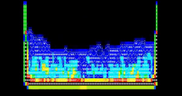
Although this animated ASCII fluid dynamics simulator dates back to 2012, it’s just too cool not to share. It’s the product of the International Obfuscated C Code Contest (IOCCC). A contest held each year where the goal is to write the most confusing C code that you can – making use of loopholes and ambiguity in the C programming language to obfuscate(hide) the purpose of the program. Basically, doing everything you’re taught not to do in school. You can take a look at the source code here.

We’re sure the programmer [Yusuke Endoh] would be the first to admit, that there is no practical use for such a low resolution simulator, but we give it an A+ in the retro cool department anyways. (Not to mention, the source code is way too confusing to even comment on) Take a look at the animated ASCII graphics in the video after the break.

Continue reading “Animated ASCII Fluid Dynamics Simulator Is Retro Cool”

Adam Savage’s First Order Of Retrievability Tool Boxes

Let’s face it, we’re all a bit obsessed with tools. Whether it’s an oscilloscope or a screwdriver, having just the right tool can be the difference between loving what you are doing, or dreading it. But oddly enough, not much is talked about tool organization. We tend to think that how you organize your tools is just as import as the tools themselves.

[Adam Savage] of Mythbusters fame might just be the king of tool organization. In this thread on the Replica Props Forum, [Adam] shares the design and construction of two sets of mobile tool boxes he built while working at Industrial Light and Magic. The idea is simple: First Order Retrievability. That is, you should never have to move one tool to get to another. That in turn affords the fastest, most efficient way of working.

The evolution of this idea started with medical bags (the kind doctors would use, back in the day when doctors still made house calls), but as [Adam’s] tool collection grew, the leather was no match for 50 pounds of tools. So, he stepped up to two aluminum tool boxes. Adding wheels and a scissor lift allowed for a moveable set, at just the right height, that are always in reach. Perfect for model making, where being able to move to different parts of a model, and taking your tools with you is key. If you’re looking for a list of what’s inside [Adam]’s box of wonder, here you go.

What are some of your favorite ways of organizing your tools? What tips or tricks do you have? Post a picture or description in the comments.  I’m sure we all could learn a bit from one another.

Custom Case Made Entirely Out Of PCBs

So you’ve finished your project. You’ve got a wonderful circuit, a beautiful PCB, and everything works perfectly. You’re done right? Well, maybe not. Sure, a bare PCB might be fine for a dev board, but what if you have a LCD to mount, a knob that needs turning, and buttons that need pressing. Yeah, that potentiometer hanging off the board by a few wires isn’t so pretty, is it? So it’s time for a case. Yuck. We all hate modifying cases.

[Electrodacus] came up with a clever solution in the form of stacking PCBs to form a case. In his project, he actually has the circuitry spread across 3 PCBs, and uses surface mount connectors to connect them in a stack. Along the edges are specifically shaped PCBs to complete the enclosure. This technique could be used with only one PCB containing all the circuitry, and the others acting as the case sides and top.

In this solar battery management project, the base layer has most of the power circuitry. This layer uses an aluminum metal core PCB for heat dissipation. The center layer is home for the micro controller and supporting components. And the top layer is the “front panel” with capacitive touch buttons and a cut out for a LCD. The top layer silk screen contains the logo, button markings, and the pin out of all the connectors.

If you hate drilling and filling cases (as much as we do), this technique might be right for your next project.

[via EEVBlog Forums]

Openhand Combines 3D Printing With Urethane Casting

Yale University brings us quite a treat with their Openhand Project.

If you’ve ever operated a robotic arm, you know that one of the most cumbersome parts is always the end effector. It will quickly make you realize what an amazing work of engineering the human hand really is, and what a poor intimation a simple open-close gripper ends up being.

[Yale] is working to bring tendon-driven robotic hands to the masses with an interesting technique of combining 3D printing and resin/urethane casting. Known as Hybrid Deposition Manufacturing (HDM), it allows the team to 3D print robotic fingers that also contain the mold for finger pads and joints, all built right into the 3D part.  The tendon-driven fingers allow for a very simple design that are not only easy to make, but have a low parts count as well. Because of the human-like tendons, the fingers naturally curl around the object, distributing it’s force much more evenly and naturally, much like a human hand would. In the videos after the break, you can see the building process, as well as the hand in action.

Best news is that it’s all open source. They also include some python libraries so you can customize the CAD files fit your needs.

Continue reading “Openhand Combines 3D Printing With Urethane Casting”

DIY Through Hole Plating Like A Boss

We’ve seen plenty of professional looking, homemade PCBs over the years. But this is the first time we’ve seen such professional vias and through hole plating. Don’t let the green solder mask fool you. This is a homemade PCB.

[Kurt Skauen] started with your standard artwork, followed by etching. He then applied a solder mask that is UV curable. At this point, it’s nothing we haven’t seen done before. After drilling he then adds vias with wire. Again, we’ve seen that before as well. Where it gets interesting is his use of through hole plating rivets. We’ve heard of these micro-sized rivets in the past, but hadn’t seen their use documented as well as [Kurt] has.

Making such a professional looking board at home is practically an art form. One could argue that with today’s cheap, short run PCB fab houses, why bother with trying to do it yourself? Well, perhaps you need a professional looking board to show a client ASAP. Maybe you just hate waiting for your boards to arrive. Or maybe you do it just because you can. Either way, the results [Kurt] achieved are very impressive.

Use The Force, Luke…to Turn Off Your TV

Have you ever wanted to turn on or off your TV just by thinking about it? We love this hack mainly because it uses an old Star Wars Force Trainer game. You can still buy them for about $40-$80 USD online. This cool little toy was introduced in 2009 and uses a headset with electrodes, and an electroencephalography (EEG) chip. It transmits the EEG data to control a fan that blows air into a tube to “levitate” a ball, all the while being coached on by the voice of Yoda. (Geesh! Kids these days have the best toys!)

[Tinkernut] started by cracking open the headset, where he found the EEG chip made by a company called NeuroSky (talk about a frightening sounding company name). The PCB designer was kind enough to label the Tx/Rx pins on the board, so hooking it up to an Arduino was a snap. After scavenging an IR LED and receiver from an old VCR, the hardware was just about done. After a bit of coding, you can now control your TV by using the force! (Ok, by ‘force’ I mean brainwaves.)  Video after the break.

Note: [Tinkernut’s] blog page should have more information available soon. In the meantime if you can find his Arduino Brain Library on github.

This isn’t the first EEG to TV interface we’ve featured. Way back in 2010 we featured a project that used an Emotiv EPOC EEG headset to turn on and off a TV. But at $400 for the headset, it was a little too expensive for the average Jedi.

Continue reading “Use The Force, Luke…to Turn Off Your TV”

How I Learned To Stop Worrying And Love My 3D Printer

So, you’re thinking about finally buying a 3D printer? All the cool kids have one. Plus, how hard can it be anyways? Well, before you pull the trigger, it might be best to read this cautionary tale of one user’s experience in getting started with his first 3D printer.

[Scott Hanselman] is a programmer and teacher who started out with zero knowledge of 3D printing. In his informative (and somewhat humorous) blog post, you can follow along with [Scott] hour-by-hour as he unravels the some of the common mysteries that almost everyone will encounter with their first 3D printer.

His adventure begins with the frustration of z-axis calibration, an important part of any 3D printer. Some of the newer printers are automating this step (as well as bed-leveling) with sensors and clever software, but even then it might need small tweaks to lay down the all-important first layer. By hour five with his new printer, this slight annoyance turns into disgruntlement, as he finds that although there is tons of documentation on-line, a lot of it can be outdated or simply unhelpful.

In the end, [Scott] got his printer up and running, and learned a lot along the way.  We bet you can too – with a little effort that is. As the quality of printers on the market keeps going up, and the price continuing to fall for an entry-level printer, now might be the perfect time for you to get started. But you might want to read [Scott’s] journey to help manage your out-of-the-box expectations.