Using Spiral Mode To Rapidly Print Enclosures

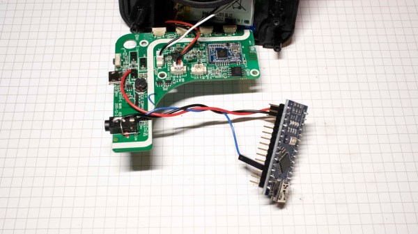
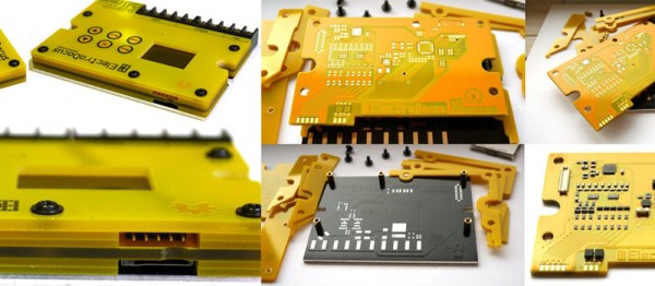
We’ve often said that one of the best applications of desktop 3D printing is the production of custom enclosures. A bespoke case adds a touch of professionalism to any project, and considering the materials needed to print one will cost less than even the cheapest generic project box, it’s a no-brainer. There’s only one problem: it can take hours to print even a simple case.

To try and speed things up, [Electrobob] has been experimenting with running off enclosures using spiral or “vase” mode on his 3D printer. Unlike the normal layer-by-layer approach, in this mode, the printer’s hotend continually rises at a steady rate during the entire print. Think of it as akin to printing out a Slinky and you should get the idea.

Spiral printed boxes may need manual retouching

As you might expect, there are some trade-offs here. For one, the walls of the box can’t be very thick since the printer is only making one pass. The nozzle on most printers is 0.4 mm, but in his experiments, [Electrobob] has found he’s able to reliably double that to a wall thickness of 0.8 mm by adjusting the extrusion rate.

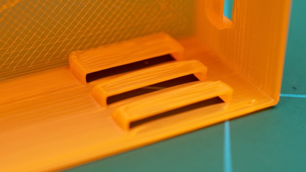
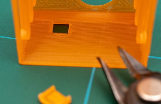
You also need to approach the design a bit differently during the CAD phase. Printing holes in the side of the enclosure, which would be easy enough to do normally, doesn’t really work when running in spiral mode. For those situations, [Electrobob] recommends designing a “pocket” into the side that you can come back and cut out with a knife. It will add a little time to the post-processing stage, but the time saved during the print will more than make up for it.

So how much faster are we talking about? In the example [Electrobob] shows in his write-up, the print time went from nearly two hours to just 18 minutes. The resulting enclosure obviously looks a bit different than the traditionally printed version, and isn’t as strong, but the concept still clearly holds promise for some applications. If you’re building a sensor network that needs a bunch of enclosures, those time savings will really add up.

How To Hack A Portable Bluetooth Speaker By Skipping The Bluetooth

Portable Bluetooth speakers have joined the club of ubiquitous personal electronics. What was once an expensive luxury is now widely accessible thanks to a prolific landscape of manufacturers mass producing speakers to fit every taste and budget. Some have even become branded promotional giveaway items. As a consequence, nowadays it’s not unusual to have a small collection of them, a fertile field for hacking.

But many surplus speakers are put on a shelf for “do something with it later” only to collect dust. Our main obstacle is a side effect of market diversity: with so many different speakers, a hack posted for one speaker wouldn’t apply to another. Some speakers are amenable to custom firmware, but only a small minority have attracted a software development community. It doesn’t help that most Bluetooth audio modules are opaque, their development toolchains difficult to obtain.

So what if we just take advantage of the best parts of these speakers: great audio fidelity, portability, and the polished look of a consumer good, to serves as the host for our own audio-based hacks. Let’s throw the Bluetooth overboard but embrace all those other things. Now hacking these boxes just requires a change of mindset and a little detective work. I’ll show you how to drop an Arduino into a cheap speaker as the blueprint for your own audio adventures.

Continue reading “How To Hack A Portable Bluetooth Speaker By Skipping The Bluetooth”

Designing Your Project To Scale: Crossing The Chasm

Hackaday is all about the neat hacks and the repurposing of old components into new projects, but many people then try to take those projects and turn them into businesses. We’ve seen lots of people offer their stuff as kits and sell them on Tindie, with the rare few going on to develop a consumer electronic product at scale.

The Hackaday Prize 2017 Best Product highlights this journey. “Scale” itself is a vague term, but essentially it means to be able to produce enough to meet market demand. We hope that market demand is roughly 7 billion units, purchasing yearly, but the reality is that it is somewhere between 1 and a few hundred thousand, with very big differences in manufacturing at each order of magnitude. So how do you start with a proof of concept and design your product from the very beginning to be optimized to scale to meet whatever demand you can handle?

Continue reading “Designing Your Project To Scale: Crossing The Chasm”

Custom Case Made Entirely Out Of PCBs

So you’ve finished your project. You’ve got a wonderful circuit, a beautiful PCB, and everything works perfectly. You’re done right? Well, maybe not. Sure, a bare PCB might be fine for a dev board, but what if you have a LCD to mount, a knob that needs turning, and buttons that need pressing. Yeah, that potentiometer hanging off the board by a few wires isn’t so pretty, is it? So it’s time for a case. Yuck. We all hate modifying cases.

[Electrodacus] came up with a clever solution in the form of stacking PCBs to form a case. In his project, he actually has the circuitry spread across 3 PCBs, and uses surface mount connectors to connect them in a stack. Along the edges are specifically shaped PCBs to complete the enclosure. This technique could be used with only one PCB containing all the circuitry, and the others acting as the case sides and top.

In this solar battery management project, the base layer has most of the power circuitry. This layer uses an aluminum metal core PCB for heat dissipation. The center layer is home for the micro controller and supporting components. And the top layer is the “front panel” with capacitive touch buttons and a cut out for a LCD. The top layer silk screen contains the logo, button markings, and the pin out of all the connectors.

If you hate drilling and filling cases (as much as we do), this technique might be right for your next project.

[via EEVBlog Forums]