One of the most widely recognised product brands in the world is probably Coca-Cola, and its formula is famously kept a secret through precautions that probably rival those of many nation states. There are other colas, and there are many amateurs who have tried to copy Coke’s flavour, but in well over a century, nobody has managed it. Why does [LabCoatz] think his attempt will be successful where others failed? He has friends with their own mass spectrometers.
Emulating older computers on microcontrollers has been a staple of retrocomputing for many years now, with most 8-bit and some 16-bit machines available on Atmel, ARM, or ESP32 platforms. But there’s always been a horsepower limit, a point beyond which a microcontroller is no longer enough, and a “proper” computer is needed. One of those barriers now appears to have been broken, as microcontroller-based emulation moves into the 32-bit era. [Amcchord] has the Basilisk II emulator ported to the ESP32-P4 platform, providing a 68040 Mac able to run OS8.1. This early-1990s-spec machine might not seem like much in 2026, but it represents a major step forward.
The hardware it uses is the M5Stack Tab5, and it provides an emulated Mac with up to 16 MB of memory. Remember, in 1992 this would have been a high-spec machine. It manages a 15 frames per second refresh rate, which is adequate for productivity applications. The emulator uses the Tab5’s touchscreen to emulate the Mac mouse alongside support for USB input devices. To 1990 hackers, it’s almost the Mac tablet you didn’t know you would want in the future.
We like this project, both because it’s advancing the art of emulation on microcontrollers, and also because it delivers a computer that’s useful for some of the things you might have done with a Mac in 1992 and could even do today. Pulling this out on the train back then would have blown people’s minds. There’s even a chance that MacOS on something like this would turn a few heads in 2026. It’s certainly not the first emulated Mac we’ve seen though.
A Vector Network Analyser, or VNA, is the ultimate multi-tool of RF test equipment. They can now be had in not very capable form for almost pocket money prices, but the professional-grade ones cost eye-watering sums. Enough to make an older VNA for a few hundred on eBay a steal, and [W3AXL] has just such a device in an HP 8714C. It’s the height of 1990s tech with a floppy drive and a green-screen CRT, but he’s homing right in on the VGA monitor port on the back. Time for a colour LCD upgrade!
There are two videos below the break, posted a year apart, because as we’re sure many of you will know, events have a habit of getting in the way of projects. In the first, we see the removal of the CRT module and safe extraction of its electronics, followed by the crafting of a display bezel for the LCD. Meanwhile, the second video deals with the VNA itself, extracting the VGA signal and routing it forward to the new module. Continue reading “A 1990s VNA Gets An LCD”→
There’s an old adage in photography that the best camera in the world is the one in your hand when the shot presents itself, but there’s no doubt that a better camera makes a difference to the quality of the final image. Among decent quality cameras the Leica rangefinder models have near cult-like status, but the problem is for would-be Leica owners that they carry eye-watering prices. [Cristian Băluță] approached this problem in s special way, by crafting a Leica-style body for a Panasonic Lumix camera. Given the technology relationship between the Japanese and German companies, we can see the appeal.
While the aesthetics of a Leica are an important consideration, the ergonomics such as the position of the lens on the body dictated the design choices. He was fortunate that the internal design of the Lumix gave plenty of scope for re-arrangement of parts, given that cameras are often extremely packed internally. Some rather bold surgery to the Lumix mainboard and a set of redesigned flex PCBs result in all the parts fitting in the CNC machined case, and the resulting camera certainly looks the part.
The write-up is in part a journey through discovering the process of getting parts manufactured, but it contains a lot of impressive work. Does the performance of the final result match up to its looks? We’ll leave you to be the judge of that. Meanwhile, take a look at another Leica clone.
Many projects on these pages do clever things with video. Whether it’s digital or analogue, it’s certain our community can push a humble microcontroller to the limit of its capability. But sometimes the terminology is a little casually applied, and in particular with video there’s an obvious example. We say “PAL”, or “NTSC” to refer to any composite video signal, and perhaps it’s time to delve beyond that into the colour systems those letters convey.
Know Your Sub-carriers From Your Sync Pulses
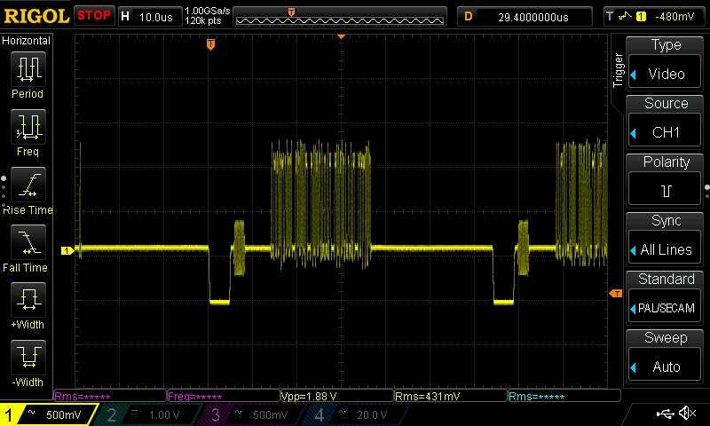
A close-up on a single line of composite video from a Raspberry Pi.
A video system of the type we’re used to is dot-sequential. It splits an image into pixels and transmits them sequentially, pixel by pixel and line by line. This is the same for an analogue video system as it is for many digital bitmap formats. In the case of a fully analogue TV system there is no individual pixel counting, instead the camera scans across each line in a continuous movement to generate an analogue waveform representing the intensity of light. If you add in a synchronisation pulse at the end of each line and another at the end of each frame you have a video signal.
But crucially it’s not a composite video signal, because it contains only luminance information. It’s a black-and-white image. The first broadcast TV systems as for example the British 405 line and American 525 line systems worked in exactly this way, with the addition of a separate carrier for their accompanying sound. Continue reading “How Do PAL And NTSC Really Work?”→
We are all familiar enough by now with the succession of boards that have come from Raspberry Pi in Cambridge over the years, and when a new one comes out we’ve got a pretty good idea what to expect. The “classic” Pi model B+ form factor has been copied widely by other manufacturers as has their current Compute Module. If you buy the real Raspberry Pi you know you’ll get a solid board with exceptionally good software support.
Every now and then though, they surprise us, with a board that follows a completely different path, which brings us to the one on our bench today. The Compute Module Zero packs the same quad-core RP3 system-on-chip (SoC) and Wi-Fi module as the Pi Zero 2 W with 512 MB of SDRAM onto a tiny 39 mm by 33 mm postage-stamp module. It’s a Pi, but not as you know it, so what is it useful for? Continue reading “Hands On WIth The Raspberry Pi Compute Module Zero”→
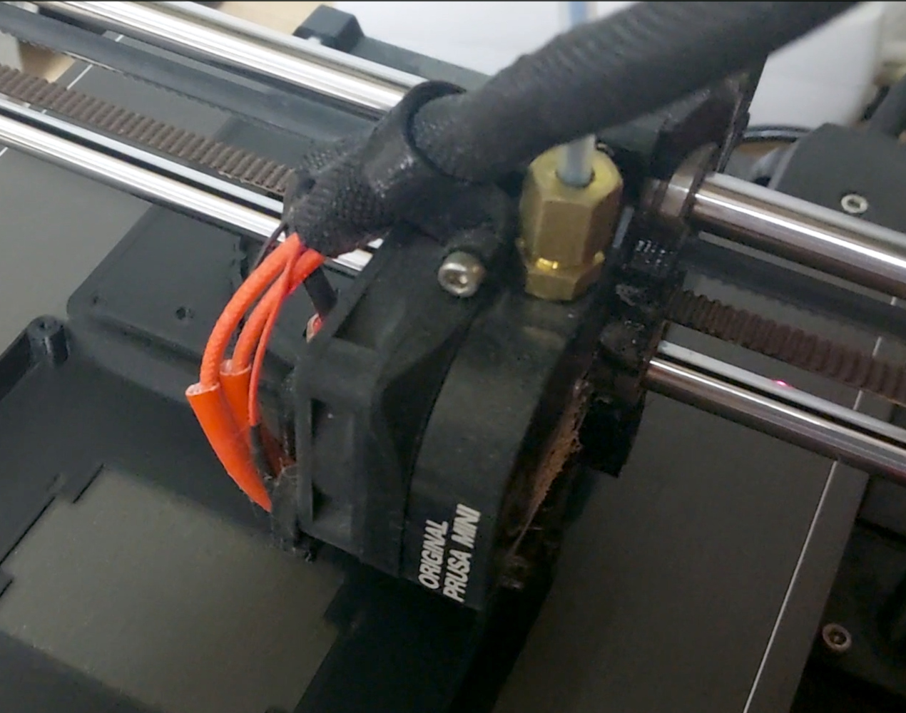
A friend of mine and I both have a similar project in mind, the manufacture of custom footwear with our hackerspace’s shiny new multi-material 3D printer. It seems like a match made in heaven, a machine that can seamlessly integrate components made with widely differing materials into a complex three-dimensional structure. As is so often the case though, there are limits to what can be done with the tool in hand, and here I’ve met one of them.
I can’t get a good range of footwear for my significantly oversized feet, and I want a set of extra grippy soles for a particular sporting application. For that the best material is a rubber, yet the types of rubber that are best for the job can unfortunately not be 3D printed. In understanding why that is the case I’ve followed a fascinating path which has taught me stuff about 3D printing that I certainly didn’t know.
Newton strikes back, and I can’t force rubber through this thing.
A friend of mine from way back is a petrochemist, so I asked him about the melting points of various rubbers to see if I could find an appropriate filament His answer, predictably, was that it’s not that simple, because rubbers don’t behave in the same way as the polymers I am used to. With a conventional 3D printer filament, as the polymer is fed into the extruder and heated up, it turns to liquid and flows out of the nozzle to the print. It ‘s then hot enough to fuse with the layer below as it solidifies, which is how our 3D prints retain their shape. This property is where we get the term “plastic” from, which loosely means “Able to be moulded”.
My problem is that rubber doesn’t behave that way. As any casual glance at a motor vehicle will tell you, rubber can be moulded, but it doesn’t neatly liquefy and flow in the way my PLA or PET does. It’s a non-Newtonian fluid, a term which I was familiar with from such things as non-drip paint, tomato ketchup, or oobleck, but had never as an electronic engineer directly encountered in something I am working on. Continue reading “Why Can’t I 3D Print With Rubber?”→