
Generally the idea with photopolymers as used with resin 3D printing is that the process only works in a single direction as with all thermosets: after polymerization under influence of UV light they become an inert lump of plastic. Being able to turn these lumps back into resin would of course be ideal, as it would make recycling incredibly easy. Here depolymerizable resin turns out to be a thing, with 3Dresyn being one company that sells additives and resin which enable this (found via Fabbaloo).
These additives and resins come in essentially two flavors based on which temperature they depolymerize at, which can be at either 80°C or 150°C. This comes at a cost, of course, with the ready-to-use resin coming in at an eyewatering €833.00 for a 1 kg bottle, a factor only slightly helped by the reusability aspect.
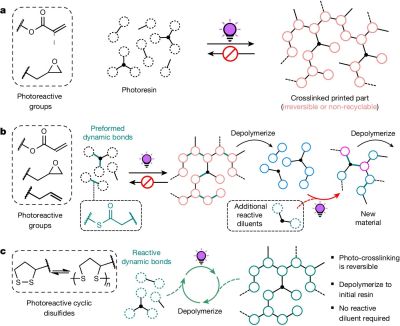
From a more technical perspective this depolymerization feature is fascinating, as it addresses the one aspect of thermosets (like SLA and epoxy resins) that thermoplastics have as advantage, especially from a recycling view. This type of circular photopolymer appears to be quite novel, with an article by [Machado] et al. from 2024 claiming to have demonstrated the first resin that can be photopolymerized, depolymerized and subsequently again photopolymerized in a closed loop.
In the demonstration by [Machado] et al. the depolymerization is achieved using dynamic disulfide bonds, with the pulverized printed samples put into a 2-methyl-tetrahydrofuran (MeTHF) solvent. After heating at 80°C for 3 hours with an inert atmosphere, most of the photopolymerized material had returned to its original, pre-printing state. In a more recent 2025 study by [Bo Yang] et al. an approach using catalytic thermal dissociation of dithioacetal bonds was explored.
Based on the available information by 3Dresyns it would seem that their product is closer to this latter approach, with depolymerization requiring putting the part into an oven at the target temperature for up to an hour, presumably in some kind of suitable container. This is said to target elements like sacrificial molds, reusable tooling and jigs that would otherwise be discarded, or need to melt like a thermoplastic instead of acting like a thermoset. Whether a solvent like MeTHF is required as in the two cited studies is sadly unclear based on a quick scan of the site.
Thanks to [SpillsDirt] for the tip.


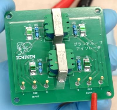 The finished ground loop isolator device is pretty large, and would definitely require a larger enclosure than the homeopathic device, but it makes for an easy test bed with convenient access during the subsequent analysis.


