Class-D Audio Amplifier Makes It From Breadboard To PCB

[Ben Laskowski’s] been working on a Class-D audio amplifier for several months. What you see above is the most recent version of the amp. A class-D amplifier uses transistor switching (or in this case MOSFET switching) to generate the pulse-width-modulated signal that drives the speaker. This is different from common amplifiers as it doesn’t generate the kind of heat that traditional amplifiers do, making it much more efficient.

After the break you can hear it demonstrated. It’s operating off of a single-supply laptop brick and we do hear a bit of a hum coming through the system. Still, we’re quite pleased at the power and quality the small board can put out. Take a look at a post from November to get a handle on what went into development. If you still hunger for more details, [Ben’s] shared the bulk of his prototyping materials in the github repository.

Continue reading “Class-D Audio Amplifier Makes It From Breadboard To PCB”

Xoscillo Turns Arduino In An Oscilloscope

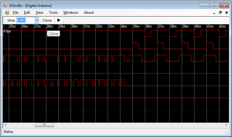
If you don’t have an oscilloscope you’d be surprised how many times you find yourself needing one. But if you have an Arduino on hand, the next time you might be able to get by with this software suite that can use a development board as oscilloscope inputs. The project is called xoscillo, and it allows an Arduino, or a Parallax USB Oscilloscope, to probe the signals while a computer does the heavy lifting.

The Arduino can be used for up to four input channels at 7 kHz. It’s possible to probe seven signals at 4 kHz as well. But the main feature that caught our eye is the ability to use several Arduino boards at one time in increase the number of channels available to you.

Granted, this is pretty slow for many digital electronic troubleshooting needs. But at least it’s something you can pull out when you just don’t have any other ideas about what is going wrong with your prototype circuit. We’re sure that sooner or later you’ll break down and buy a proper hackable oscilloscope. After all, your Arduino is probably already occupied as an I2C sniffer.

[Thanks Adam]

NES Multi-cartridge

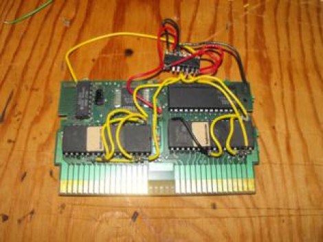
Here’s a mutlicartridge hack for the original NES that [Callan Brown] put together. He spent some time snooping around the signals on the circuit board seen above until he found the trace that maps the reset signal from the game console. This will be used to cycle through the various games stored on the cart’s memory chip. The ROM images that will be stored on this cartridge are concatenated, then burned to the EPROM. Since the donor cartridge (and the ROMs which were chosen) use memory managment, the hardware can be tricked into reading the ROM from a specific point in the EPROM.

The switching itself is handled by a 74HC161 binary counter chip. The reset signal from the on-board security chip acts as a clock trigger for the counter. Some clever wiring allows the output of the counter to select the starting address for the EPROM. Each time you press the reset button it increments the counter, thereby selecting a different ROM to load. See [Callan] demonstrate the finished hack in the video after the break.

Continue reading “NES Multi-cartridge”

Reverse Engineering A Cheap LED Message Marquee

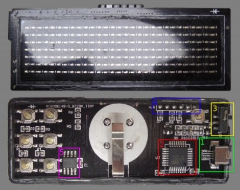
[Hugo] went all out when sharing his findings while reverse engineering this small LED marquee. He purchased the 29×7 LED matrix for under $12 but was surprised to find that the USB connector wasn’t a standard type and didn’t come with a cable. He first soldered a standard connector in place and then set out to make the device do his bidding (translated).

What he accomplished can be seen in the video after the break. He can now connect to the device via a USB cable, sending it new messages and adjusting the speed at which it scrolls. He can also adjust the spacing between letters, reverse the scrolling direction, read the on-board buttons, and write the settings to the device’s EEPROM. This is all thanks to some alternative firmware that [Hugo] wrote for the ATmega88. You can download a copy of that code from the wiki page he put together (translated). We really appreciate the time he spent putting that page together. The wealth of information he gathered during the hacking process serves as an example of the best way to share your projects with the world.

Continue reading “Reverse Engineering A Cheap LED Message Marquee”

An Alarm For Every Day Of The Week

If you don’t have a 9-to-5 type of job you might find yourself constantly resetting your alarm clock as your calendar commitments change. [Lucas] finally got fed up with the nightly ritual and decided to build his own alarm clock which has unique settings for each day of the week (translated).

The display itself is an LM044L 20×4 character display. This provides a viewing area that is about 3″x1″ and since it’s an HD44780 compliant LCD screen, writing data to it takes very little effort (and RAM) compared to a graphic LCD. A PIC 18F2550 drives the device, taking input from a half-dozen buttons, driving the display, and turning on the enclosed buzzer when it’s time to get up. There’s a backup battery which will keep the settings when power is lost. The daily alarms, current time, and back light brightness can all be adjusted from the four screens that make up the settings menus. The only thing that it’s missing is a precision timekeeper, but that should be easy to add either by measuring the frequency of the mains or by using an RTC chip.

Dimming Control For An Ikea Solar Desk Lamp

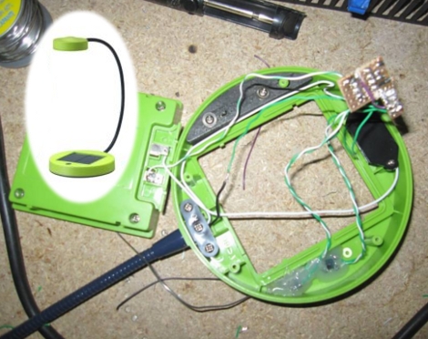
[Frank] decided to augment his desk lamp’s features by adding dimming controls (translated). Since the light source is a triad of LEDs the best method of dimming their intensity is to use Pulse Width Modulation. That’s the method that he went with, and luckily the SUNNAN lamp from Ikea which he’s using as the donor for the project has just enough room to squeeze in the parts necessary for this hack.

You need two main bits to use PWM with a lamp like this; a microcontroller (or possibly a timer chip like the 555) and a transistor to protect that chip from the current necessary to run the LEDs at full brightness. [Frank] went with an ATtiny13 and a 2N2222 transistor, both quite common and very inexpensive (you can even pull the microcontroller from a light bulb if you know where to look). Two buttons were added to the top of the lamp base which allow for up and down controls. There’s even an SOS function which is triggered by pressing both buttons at the same time. [Frank’s] happy to show off the completed project in the clip after the break.

Continue reading “Dimming Control For An Ikea Solar Desk Lamp”

Adding Ethernet Control For A 5.1 Speaker Set

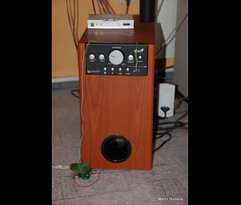
[HuB’s] set of 5.1 surround sound speakers was gobbling up a bunch of electricity when in standby as evidenced by the 50 Hz hum coming from the sub-woofer and the burning hot heat sink on the power supply. He wanted to add a way to automatically control the systems and offer the new feature of disconnecting the power from the mains.

The first part was not too hard, although he used a roundabout method of prototyping. He planned to use the IR receiver on the speakers to control them. At the time, [HuB] didn’t have an oscilloscope on hand that he could use to capture the IR protocol so he ended up using Audacity (the open source audio editing suite) to capture signals connected to the input of a sound card. He used this to establish the timing and encoding that he needed for all eight buttons on the original remote control.

Next, he grabbed a board that he built using an ATmega168 and an ENC28J60 Ethernet chip. This allows you to send commands via the Internet which are then translated into the appropriate IR signals to control the speakers and a few other devices in the room. The last piece of the puzzle was to wrap an RF controlled outlet into the project with lets him cut mains power to the speakers when not in use. You can see the video demonstration embedded after the break.

Continue reading “Adding Ethernet Control For A 5.1 Speaker Set”