Why do only the new game consoles get all the cool peripherals? Being a man of action, [Paul] set out to change that. He had a Kinect V2 and an original Nintendo and thought it would be fun to get the two to work together.
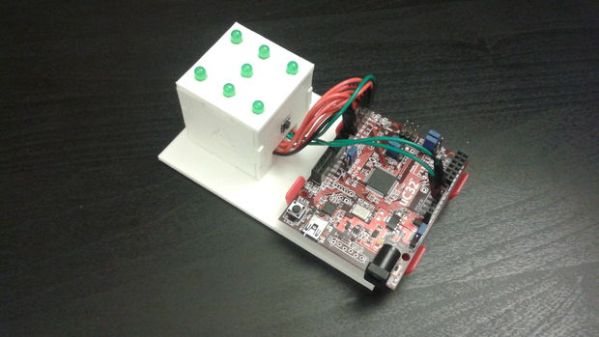
Thinking it would be easiest to emulate a standard controller, [Paul] surfed the ‘net a bit until he found an excellent article that explained how the NES controller works. It turns out that besides the buttons, there’s only one shift register chip and some pull up resistors in the controller. Instead of soldering leads to a cannibalized NES controller, he decided to stick another shift register and some resistors down on a breadboard with a controller cable connected directly to the chip.
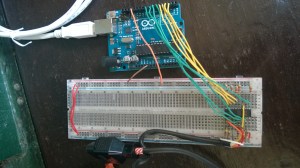
An Arduino is used to emulate the buttons presses. The Arduino is running the Firmata sketch that allows toggling of the Arduino pins from a host computer. That host computer runs an application that [Paul] wrote himself using the Kinect V2 SDK that converts the gestures of the player into controller commands which then tells the Arduino which buttons to ‘push’. This is definitely a pretty interesting and involved project, even if the video does make it look very challenging to rescue Princess Toadstool from Bowser and the Koopalings!
If you’d like to help the project or just build one for yourself, check out the source files on the Kinect4NES GitHub page.
Continue reading “Using Kinect To Play Super Mario Bros 3 On NES Ensures Quick Death”
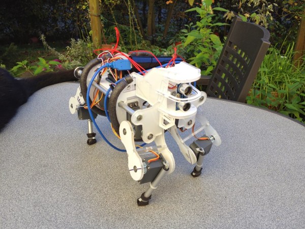
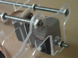 [Max] designed all of the mechanical parts himself. After weighing the advantages and disadvantages of different materials, he decided that the frame would be made from 5mm acrylic sheet. The main body of the robot has acrylic ribs that are spaced apart by threaded rods. Twelve RC servos make up all of the joints, 3 in each leg. Notice in this photo how there is one servo that immediately rotates another servo. To support the other side of the rotating servo, [Max] epoxied on a T-nut, stuck in a short length of threaded rod which is then supported in the frame by a ball bearing. Simple and effective! The upper portions of the legs are also made from acrylic sheet and the lower legs are from a cheap camera tripod. Rubber feet ensure a slip resistant stance.
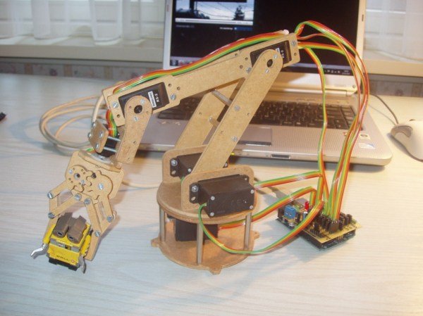
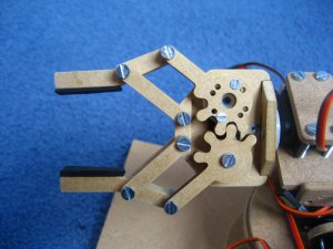 Like any project, there were some hiccups along the way. First, several revisions of the gripper were necessary to get the correct tooth profile that resulted in smooth and tight movement. Also, while making the shield the spacing between banks of headers came out one header too close! On this first board [jjshortcut] just bent the pins so they would fit into the Arduino. You can’t let some minor snafu prevent forward momentum of a project!
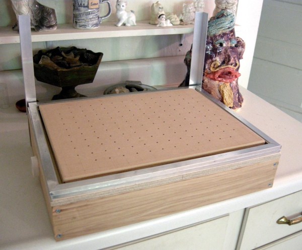
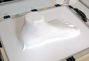
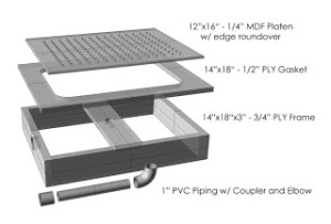 There is a two-pronged attack to keep the costs down on this project. First, the frame is made from readily available materials that you probably have kicking around in your wood scrap bin. The sides of the frame are 3/4″ plywood and the hole-filled top is made from 1/4″ MDF. A piece of PVC pipe connects the chamber below the top piece of MDF to a shopvac. The shopvac pulls the air down through the top’s holes; think reverse air hockey table.