Learning To Reverse Engineer On A Broken Printer

Lexmark Hack

When a Lexmark inkjet printer stopped working, [Mojobobo] was able to claim it as his own. He quickly realized that the machine was flooded with ink and not worth repairing, but that didn’t mean he couldn’t still find a use for it. When he learned that the printer’s firmware was not only upgradable but also unprotected, he knew he should be able to get the printer to do his own bidding.

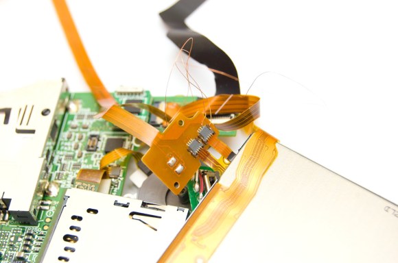
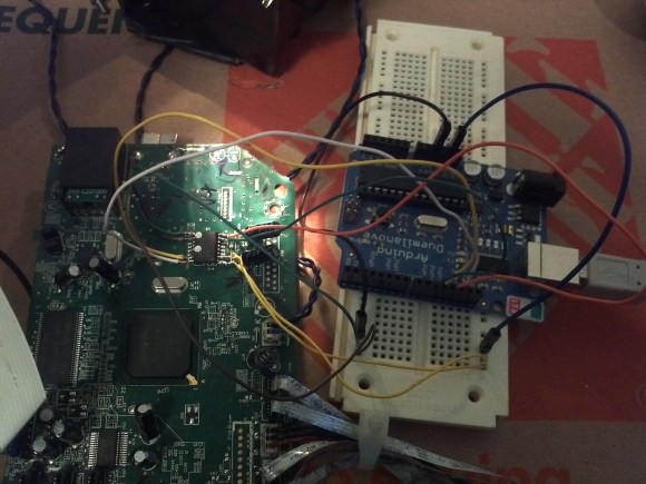
[Mojobobo] started his journey with the motherboard. The unit still powered up, but it was asking to insert a “duplex module” before it would boot any further. [Mojobobo] first tried to find a way to trick the duplex module sensor, but was unsuccessful. His next step was to search for some kind of serial communications port. He didn’t have an oscilloscope, so instead he used a speaker with a wire probe. In theory, if the wire was pressed against an active serial port, he would be able to hear varying tones through the speaker. Sure enough, he found some interesting tones after probing around some ports next to a “JTAG” label. He looked up some information about the nearby chip and found that it included an SPI bus.

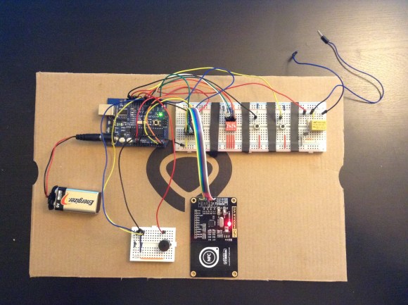
After some internet research, [Mojobobo] learned enough about SPI to have a rough idea of how to use it. Having limited tools available to him, he decided to use his Arduino to try to communicate with the motherboard. After wiring up a simple circuit, (and then re-wiring it) he was able to dump the first 4096 bytes of the motherboard’s boot loader to the Arduino via the SPI interface.

[Mojobobo’s] next steps will be to find a faster way to dump the boot loader. At 9600 baud, he grew tired of waiting after three hours. Once he has the full boot loader he intends to search for a way to bypass the duplex sensor and get the board to finish booting. Then he may just use the printer for its scanning functions, or he might find other interesting uses for it.

Electronic Puzzle Box Uses Only Discrete Components

Puzzle box

Do you need an idea for a fun do it yourself gift for a friend or significant other? Look no further, [conductance] has you covered. He put together an awesome electronic puzzle box using all analog electronics. The puzzle case is shaped like an over sized die and is made out of wood. It also requires a small jumper cable and an external magnet to complete the puzzle.

This is a six-sided die, where each side has something different to offer. The “five” side of the die shows the progress you’ve made in completing the puzzle. Each of the five dots contains a green LED that will light up when the corresponding puzzle has been successfully completed.

The “one” side is completed by placing the included magnet over the dot. The magnet activates a reed switch which lights up the first LED. The “two” side contains a tilt switch. In order to solve this piece of the puzzle you must ensure the two side is facing up, as if you rolled a two. The “three” side contains three key switches. Each switch must be turned to a particular orientation. Once all three keys are configured properly, a third LED lights up.

The “four” side contains four sockets that fit the included jumper cable. This puzzle is solved by jumping the two correct sockets together. Finally, the number “six” side just has six momentary push buttons. All six buttons must be pressed simultaneously in order to light up the final LED. The tricky part is pressing all six buttons while simultaneously “rolling” a two in order to ensure the tilt switch is also activated.

Once all five LED’s are lit up, a relay is triggered which then activates a solenoid. The solenoid unlocks the door and reveals the prize. It’s always great to see electronics circuits like this that use all discrete components. This could have been accomplished any number of ways, but there’s something satisfying about a simple circuit that’s just right for the job. Be sure to check out [conductance’s] schematic if you want to see how this puzzle works.

[via Reddit]

Upgrade Your Garage Door With Arduino And RFID

RFID Garage Door Opener

[Jason] really wanted to build an RFID controlled garage door opener and decided to turn to Arduino to get the job done. For someone who’s never worked with an Arduino before, he really seemed to know what he was doing.

The Arduino acts as the brains of the operation while an off-the-shelf NFC/RFID reader module is used to read the RFID tags. To add new keys to the system, [Jason] simply swipes his “master” RFID key. An indicator LED lights up and a piezo speaker beeps, letting you know that the system is ready to read a new key. Once the new key is read, the address is stored on an EEPROM. From that point forward the new key is permitted to activate the system.

Whenever a valid key is swiped, the Arduino triggers a relay which can then be used to control just about anything. In this case, [Jason] plans to use it to control his garage door. The system also has a few manual controls. First is the reset button. If this button is held down for two seconds, all of the keys from the EEPROM are erased. This button would obviously only be available to people who are already inside the garage. There is also a DIP switch that allows the user to select how long the relay circuit should remain open. This is configurable in increments of 100ms.

For now the circuit is wired up on a couple of breadboards, but it might be a good idea to use something more permanent. [Jason] could always take it a step further and learn to etch his own PCB’s. Or he could even design a board in Eagle CAD and order a real printed board. Don’t miss the video description of the RFID system below. Continue reading “Upgrade Your Garage Door With Arduino And RFID”

Hair Thin Wires Save A 3DS From The Landfill

Broken Nintendo 3DS

[Anton] recently acquired a broken Nintendo 3DS. When the power button was pressed, the device would start booting up only to shut back down after flashing a blue light and making a popping sound. It turns out this problem is pretty common with the 3DS.

[Anton] could have tossed this device into the landfill, but where’s the fun in that?  Instead, he cracked the device open like any self-respecting hacker would. It didn’t take him long to discover two broken flex ribbon cables. [Anton] could have then searched for replacement cables, but his inner hacker told him he could repair this himself. He carefully scraped the insulation off of the broken traces and then soldered on some hair thin wires to bridge the gap.

All that was left to do was to glue the wires securely in place and feed them back through the hinges. This project is a great example of how a little determination and know-how can keep a useful device from the landfill. If you attempt this repair yourself, you may find this 3DS teardown to be a helpful reference. What devices have you been able to save from an untimely demise?

Solderless Noise-o-Tron Kit Makes Noise At Chicago Makerfaire

Noise-o-Tron

Anyone who’s manned a hackerspace booth at an event knows how difficult it can be to describe to people what a hackerspace is. No matter what words you use to describe it, nothing really seems to do it justice. You simply can’t use words to make someone feel that sense of accomplishment and fun that you get when you learn something new and build something that actually works.

[Derek] had this same problem and decided to do something about it. He realized that in order to really share the experience of a hackerspace, he would have to bring a piece of the hackerspace to the people.  That meant getting people to build something simple, but fun. [Derek’s] design had to be easy enough for anyone to put together, and inexpensive enough that it can be produced in moderate quantities without breaking the bank.

[Derek] ended up building a simple “optical theremin”. The heart of this simple circuit is an ATTiny45. Arduino libraries have already been ported to this chip, so all [Derek] had to do was write a few simple lines of code and he was up and running. The chip is connected to a photocell so the pitch will vary with the amount of light that reaches the cell. The user can then change the pitch by moving their hand closer or further away, achieving a similar effect to a theremin.

[Derek] designed a simple “pcb” out of acrylic, with laser cut holes for all of the components. If you don’t have access to a laser cutter to cut the acrylic sheets, you could always build your own. The electronic components are placed into the holes and the leads are simply twisted together. This allows even an inexperienced builder to complete the project in just five to ten minutes with no complicated tools. The end result of his hard work was a crowded booth at a lot of happy new makers. All of [Derek’s] plans are available on github, and he hopes his project will find use at Makerfaires and hackerspace events all over the world.

Rackmount RasPi Leaves No Excuse To Lose Data

RasPi backup server

[Frank] knows how important backups are for data security, but his old method of plugging a hard drive in to take manual backups every so often is not the most reliable or secure way of backing up data. He realized he was going to need a secure, automated solution. He didn’t need a full-sized computer with a ton of power; why waste electricity for something so simple? His solution was to use a Raspberry Pi as the backup computer.

The main problem he faced with the Pi was finding a way to make it rack mountable. [Frank] started with an empty 1U server case. He then had to bend a few metal plates in order to securely mount the backup drive into the case. A couple of small rubber pads help dampen any vibrations caused by the hard drive.

The computer power supply was able to put out the 12V needed for the hard disk, but not the 5V required to run the Pi. [Frank’s] solution was to use an LM2596 based switching supply to turn the 12V into 5V. He soldered the power supply wires directly to the Pi, thinking that a USB plug might vibrate loose over time. Mounting the Pi to the computer case should have been the trickiest part but [Frank] made it easy by simply gluing the Pi’s plastic case to the inside of the computer case. When all was said in done, the backup server pulls 29W under full load, 9W with the disk spinning, and only about 2W in an idle state.

On the software side of things, [Frank’s] backup box uses bash shell scripts to get the job done. The Pi connects to his main server via VPN and then the bash scripts use rsync to actually collect the files. The system not only saves backups every night, but also keeps week old backups just in case. If you are really paranoid about your backups, try hooking up a custom battery backup solution to your Pi. If a Pi just isn’t doing it for you, you can always try one of many other methods.

Oinker Is Twitter For HAMs

oinker

Have you ever wanted to send a quick message to your HAM radio buddies over the air but then realized you forgot your radio at home? [Troy] created Oinker to remedy this problem. Oinker is a Perl script that turns emails into audio.

The script monitors an email account for new messages and then uses the Festival text-to-speech engine to transform the text into audio. [Troy] runs Oinker on a Raspberry Pi, with the Pi’s audio output plugged directly into an inexpensive ham radio. The radio is then manually tuned to the desired transmit frequency. Whenever Oinker see’s a new email, that message is converted into speech and then output to the transmitter.

The script automatically appends your HAM radio call sign to the end of every message to ensure you stay within FCC regulations. Now whenever [Troy] runs into some bad traffic on the road, he can send a quick SMS to his email address and warn his HAM radio buddies to stay clear of the area.