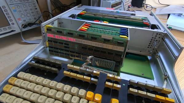
We love our retrocomputers here at Hackaday, and we’re always delighted to see someone rescue an historic artefact from the landfill. Sometimes, all it takes is replacing a broken power switch or leaky capacitor; other times you need to bring out the oscilloscope and dig deeper into internal circuitry. But the huge amount of work [Jerry Walker] put into bringing an HP 9830A back on its feet is something you don’t see very often.
If you’re not familiar with the HP 9830A, it’s a desktop computer from the early 1970s, fully built from discrete logic gates. The machine on [Jerry]’s desk turned out to be completely dead, with not even the fan spinning up. This was caused by a dodgy power switch, but replacing that switch was just the beginning: there were several bad components inside the power supply as well as a huge amount of moist dirt on the back of the motherboard. After a thorough cleaning and the replacement of several failed components, all four power rails were running within spec again.
Electromagnetic interference problems can be a real headache to debug. If you need to prove what causes your WiFi to slow down or your digital TV signal to drop, then the ability to measure electromagnetic fields (EMF) can be a big help. Professional equipment is often very expensive, but building an EMF detector yourself is not even that difficult: just take a look at Arduino expert [Mirko Pavleski]’s convenient hand-held electromagnetic field detector.
The basic idea is quite simple: connect an antenna directly to an Arduino’s analog input and visualize the signal that it measures. Because the input of an ADC is high impedance, it is very sensitive to any stray currents that are picked up by the antenna. So sensitive in fact, that a resistor of a few mega-Ohms to ground is required to keep the sensor from triggering on any random kind of noise. [Mirko] made that resistance adjustable with a few knobs and switches so that the detector can be used in both quiet and noisy environments.
Making the whole device work reliably was an interesting exercise in electromagnetic engineering: in the first few iterations, the detector would trigger off its own LEDs and buzzer, trapping itself in a never-ending loop. [Mirko] solved this by encasing the Arduino inside a closed, grounded metal box with only the required wires sticking out. The antenna’s design was largely based on trial-and-error; the current setup with a 7 cm x 3 cm piece of aluminium sheet seemed to work well.
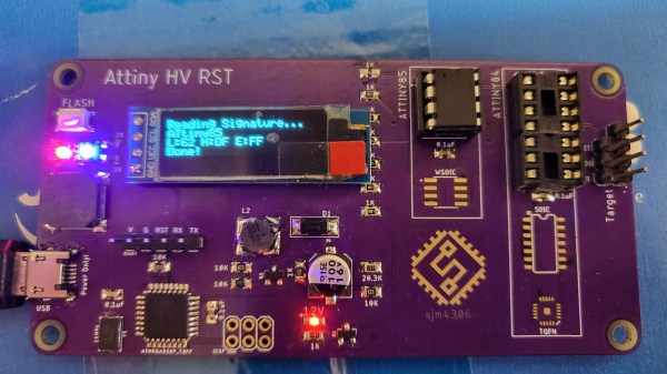
If you’re an experienced hacker, you’ve probably run into a problem at some point and thought “let’s make a tool to automate that”. A few hours later you’ve got your tool, but then realize that the amount of work you put into making the tool vastly exceeds what you would have needed to solve the original problem manually. That really doesn’t matter though: developing a fancy tool can be a rewarding experience that teaches you way more about the original problem than you would have learned otherwise. [sjm4306]’s ATtiny High Voltage Fuse Reset-er is a clever device that firmly falls into this category.
The problem it solves is familiar to anyone who’s ever worked with Atmel/Microchip’s ATtiny series of microcontrollers: set one of the configuration fuses incorrectly and you’re no longer able to reprogram your chip. Getting the ATtiny back to its original configuration requires a high-voltage programming step that involves pulling the reset pin to 12 V in what’s otherwise a 5 V system. You could simply grab a spare 12 V supply and hack together a level shifter with a few transistors, but where’s the fun in that?
[sjm4306]’s solution is built on a pretty purple PCB that contains an ATmega328, an OLED display, and sockets to accommodate various versions of the ATtiny series microcontrollers. To generate the required 12 V, one could simply use an off-the-shelf boost converter IC. But instead, he decided it would be interesting to make such a circuit out of discrete components and control it using the ATmega. After all, this chip already contains timers to generate PWM signals and an ADC to measure the converter’s output voltage, so all it took was to write some control logic in the form of a PID controller.
The end result, as you can see in the video embedded below, is a convenient little PCB that runs off a 5 V USB power supply and resets the fuses on your ATtiny at the push of a button. Sometimes, simple tools that do one thing well are all you need; however, if you’re looking for an all-in-one AVR programmer that also supports HV programming, check out this AVR Multi-Tool.
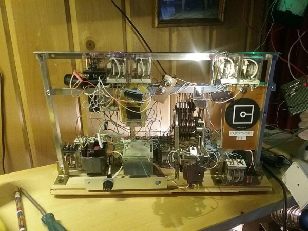
While rarely seen by users, the technology behind telephone exchanges is actually quite interesting. In the first hundred or so years of their existence they evolved from manually-operated switchboards to computer-controlled systems, but in between those two stages was a time when dialling and switching was performed electromechanically. This was made possible by the invention of the stepping switch, a type of pulse-operated relay that can connect a single incoming wire to one of many outgoing wires.
Public telephone exchanges contained hundreds of these switches, but as [dearuserhron] shows, it’s possible to make a smaller system with way fewer components: the Cadr-o-station is built around one single stepper switch. Although it looks rather complicated, the only other components are a bunch of ordinary 24 V relays and a few power supplies. Together they make up a minimal telephone exchange that connects up to ten handsets.
It doesn’t have all the functionality of a larger system however, as only a single voice circuit is made to which all phones are automatically connected. Still, it does allow users to dial a number and let the other phone ring, which might be good enough for a home or indeed the hackerspace where it’s currently sitting. It’s also a fine demonstration of how relatively simple technology can be applied to make a surprisingly complex system.
[dearuserhron] wrote an in-depth article on the workings of electromechanical telephone exchanges, which might come in helpful to anyone who’d like to design such a system for their own home. For a more general introduction into analog phone technology, check out our analysis of a 1970s rotary telephone.
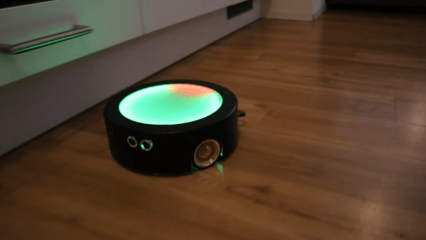
Cleaning robots are great and all, but they don’t really excel when it comes to speed. If your room looks like a pigsty and your Tinder date is arriving in twenty minutes, you’ll need more than a Roomba to make a good impression. [Luis Marx] ran into this exact problem and decided to solve it by building the world’s fastest cleaning robot (video, embedded below).
[Luis] built his ‘bot from the ground up, inspired by the design of your average robot vacuum: round, with two driven wheels and some sensors to avoid obstacles. A sturdy aluminium plate forms the chassis, onto which two powerful motors are placed to drive a pair of large-diameter wheels. The robot’s body is made from 3D-printed components and sports a huge LED display on top that functions as a speedometer of sorts.
Building a vacuum system turned out to be rather difficult, and since [Luis] already had a robot vacuum anyway, he decided to make this a robot mop instead. A little tank stores water and soap, which is pumped onto a microfibre cloth that’s attached using a magnetic strip. Obstacle avoidance is implemented through three ultrasonic distance sensors: when the robot is about to run into something it will brake and turn in the direction where it senses the most empty space.
All of that sounds great, but what about the speed? According to [Luis]’s calculations, it should be able to reach 60 km/h, although his living room is too small to put that into practice. Whether it will provide much in the way of cleaning at that speed is debatable too, but who cares: having your own ultra-high-speed robot mop will definitely impress your date more than any amount of cleaning.
We’ve featured a home-made robot mop before, but it looks excruciatingly slow compared to this one. If you’re planning to build zippy indoor robots, you might want to look into fast navigation systems like tracking ceiling lights.
One of the design requirements for the networks that evolved into the Internet was the ability to keep functioning, even if some nodes or links were disabled or destroyed in war. The packet-switched architecture that still powers today’s Internet is a direct result of that: if one link stops functioning, information is automatically re-routed towards its intended destination. However, with tech giants occupying increasingly large parts of the global internet, an outage at one of them might still cause major disruption. In addition, a large-scale power interruption can disable large parts of the network if multiple nodes are connected to the same grid.
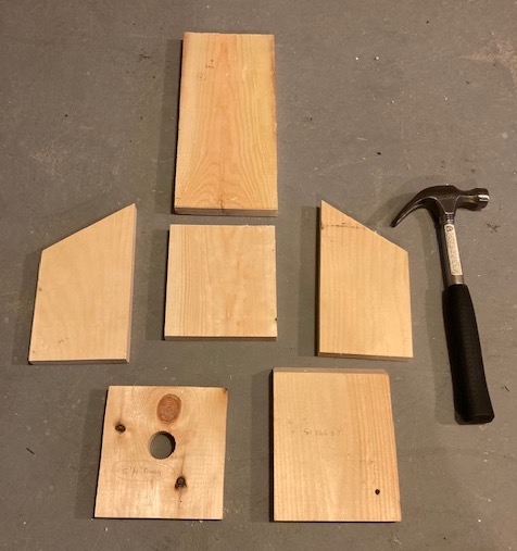
Just six pieces of wood make up the birdhouse.
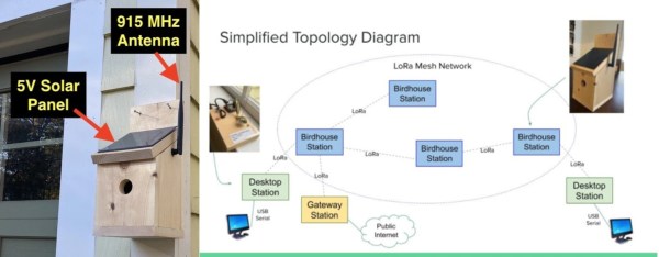
Enter the LoRa Birdhouse project by the Wellesley Amateur Radio Society that solves those two problems, although admittedly at a very small scale. Developed by amateur radio operators in eastern Massachusetts, it’s basically a general-purpose LoRa-based packet-switching network. As it’s based on open-source hardware and commonly available components, its design allows anyone to set up a similar network in their own area.
The network is built from nodes that can receive messages from their neighbors and pass them on towards their final destination. Each node contains a Semtech SX1276 transceiver operating in the 902-928 MHz band, which gets its data from an ESP32 microcontroller. The nodes are placed in strategic locations outside and are powered by solar panels to reduce their ecological footprint, as well as to ensure resilience in case of a power outage. To make the whole project even more eco-friendly, each node is built into a birdhouse that provides shelter to small birds.
Users can access the network through modified network nodes that can be hooked up to a PC using a USB cable. Currently, a serial terminal program is the only way to interact with the network, although a more user-friendly interface is being planned. FCC rules also require all users (except any avian residents) to be licensed amateur radio operators, and all traffic to remain unencrypted. Tests have shown that one kilometer between nodes can work in the right conditions, enabling the deployment of networks across reasonably large areas.
While the Birdhouse Network might not be a plug-and-play internet replacement in case of a nuclear apocalypse, it does provide an excellent system to experiment with packet-switching wireless network technology. We’ve seen similar LoRa-based network initiatives like Qmesh, Cellsol and Meshtastic, all of which provide some way to communicate wirelessly without requiring any centralized hardware.
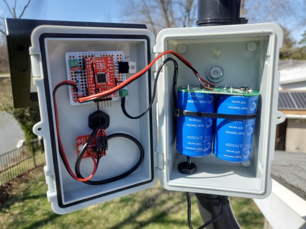
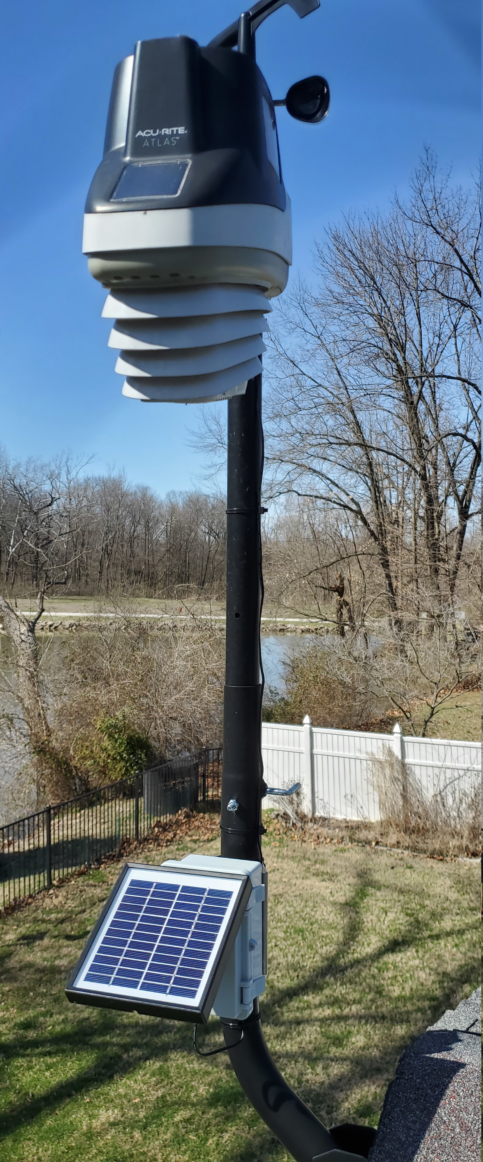
When [knight-of-ni] bought an Acurite Atlas weather station to replace his earlier 5-in-1 model, he was initally happy with its performance. However, after just ten months the batteries in the outdoor unit died; since the previous model would happily run for several years on one charge, this was a bit of a bummer. Climbing up on the roof more than once a year just to replace batteries was becoming inconvenient as well, so [knight-of-ni] designed a solar power system with supercap backup and remote monitoring that should keep the sensors running 24/7, come rain or shine.
The heart of the new power system is a pair of supercapacitors totalling 250 Farads, with an integrated protection circuit that limits the voltage to 5.4 Volts. The caps are charged by a 12 V solar panel; this means that quite a bit of power is dissipated in the protection circuit when the supercaps are fully charged, but since this is completely free solar power that is not much of an issue. A 6 V panel would have worked as well in full sunlight, but might have struggled on a cloudy or snowy day.
[knight-of-ni] wasn’t content with just letting the new power system run unattended however, and decided to integrate a remote monitoring tool as well. For this he used a Moteino, which is an Arduino-type board with an integrated 915 MHz transceiver. The data coming from this board is received by a Raspberry Pi running Linux and presented through a nice web interface. Thanks to this data [knight-of-ni] was able to confirm that the supercaps were fully charged in just an hour and a half on a sunny morning, and maybe three or four times that on a dark and rainy day.