Raspberry Pi Test Stand Tells You Which Glues To Use

Not all glues are created equal; or rather, not every glue is good for every application. But how is one to know which glue to use in which kinds of joints? The answer to that is not always clear, but solid numbers on the comparative strength of different glues are a great place to start.

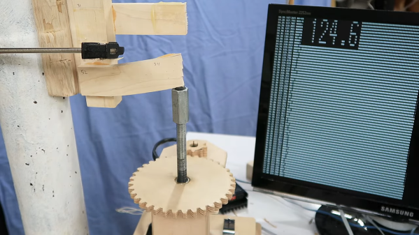
To quantify what can ordinarily be a somewhat subjective process, there’s probably no one better than woodworker and hacker [Matthias Wandel], equipped as he is with his DIY strength-tester. Using its stepper-driven power to blast apart glued lap joints, [Matthias] measured the yield point of the various adhesives using a strain gauge connected to a Raspberry Pi.

His first round of tests had some interesting results, including the usually vaunted construction adhesive ending up in a distant last place. Also performing poorly, at least relative to its reputation and the mess it can cause, was the polyurethane-based Gorilla Glue. A surprise standout in overall strength was hot glue, although that seemed to have a sort of plastic yield mode. Ever the careful empiricist, [Matthias] repeated his tests using hardwoods, with remarkably different results; it seems that glues really perform better with denser wood. He also repeated a few tests to make sure every adhesive got a fair shake. Check out the video below for the final results.

It’s always good to see experiments like this that put what we often take for granted to the test. [John] over at the Project Farm channel on YouTube does this kind of stuff too, and even did a head-to-head test of epoxy adhesives.

Continue reading “Raspberry Pi Test Stand Tells You Which Glues To Use”

Stress-Testing An Arduino’s EEPROM

Every time one of us flashes an Arduino’s internal memory, a nagging thought in the backs of our minds reminds us that, although everything in life is impermanent, nonvolatile re-writable memory is even more temporary. With a fixed number of writes until any EEPROM module fails, are we wasting writes every time we upload code with a mistake? The short answer is that most of us shouldn’t really be concerned with this unless we do what [AnotherMaker] has done and continually write data until the memory in an Arduino finally fails.

The software for this is fairly simple. He simply writes the first 256 ints with all zeros, reads them to make sure they are all there, and then repeats the process with ones. After iterating this for literally millions of times continuously over the course of about a month he was finally able to get his first read failure. Further writes past this point only accelerated the demise of the memory module. With this method he was able to get nearly three million writes before the device failed, which is far beyond the tens or hundreds of thousands typically estimated for a device of this type.

To prove this wasn’t an outlier, [AnotherMaker] repeated the test, and did a few others while writing to a much smaller amount of memory. With this he was able to push the number of cycles to over five million. Assuming the Arduino Nano clone isn’t using an amazingly high-quality EEPROM we can safely assume that most of us have nothing to worry about and our Arduinos will be functional for decades to come. Unless a bad Windows driver accidentally bricks your device.

Continue reading “Stress-Testing An Arduino’s EEPROM”

A six digit Nixie clock on a desktop

Upcycled Nixie Clock Fit For A Friend

Building a clock from parts is a rite of passage for makers, and often represents a sensible introduction into the world of electronics. It’s also hard to beat the warm glow of Nixie tubes in a desktop clock, as [Joshua Coleman] discovered when building a Nixie tube clock for a friend.

The original decision to upcycle the chassis from an unrepairable Heathkit function generator came a little undone after some misaligned cutting, so the front panel ended up being redesigned and 3D printed. This ended up being serendipitous, as the redesigned front panel allowed the Nixie tubes to be inset within the metal chassis. This effect looks great, and it also better protects the tubes from impact damage.

Sourcing clones of the 74141 Nixie driver ICs ended up being easier than anticipated, and the rest of the electronics came together quickly. The decoders are driven by an Arduino, and the IN-4 Nixie tubes are powered by a bespoke 170 volt DC power supply.

Unfortunately four of the tubes were damaged during installation, however replacements were readily available online. The gorgeous IN-4 Nixie tube has a reputation for breaking easily, but is priced accordingly on auction sites and relatively easy to source.

The build video after the break should get any aspiring Nixie clock makers started, but the video description is also full of extra information and links for those needing help getting started.

We’re not short on clock hacks here at Hackaday, so why not check out a couple more? This retro-inspired LED clock looks like its right out of a parallel universe, or maybe this stunning Nixie clock driven by relays will strike your fancy.

Continue reading “Upcycled Nixie Clock Fit For A Friend”

A weatherproof enclosure, opened to show a supercapacitor-based system inside

Wireless Weather Station Gets Solar-Powered Supercap Upgrade

When [knight-of-ni] bought an Acurite Atlas weather station to replace his earlier 5-in-1 model, he was initally happy with its performance. However, after just ten months the batteries in the outdoor unit died; since the previous model would happily run for several years on one charge, this was a bit of a bummer. Climbing up on the roof more than once a year just to replace batteries was becoming inconvenient as well, so [knight-of-ni] designed a solar power system with supercap backup and remote monitoring that should keep the sensors running 24/7, come rain or shine.

A weather station mounted on a pole outsideThe heart of the new power system is a pair of supercapacitors totalling 250 Farads, with an integrated protection circuit that limits the voltage to 5.4 Volts. The caps are charged by a 12 V solar panel; this means that quite a bit of power is dissipated in the protection circuit when the supercaps are fully charged, but since this is completely free solar power that is not much of an issue. A 6 V panel would have worked as well in full sunlight, but might have struggled on a cloudy or snowy day.

[knight-of-ni] wasn’t content with just letting the new power system run unattended however, and decided to integrate a remote monitoring tool as well. For this he used a Moteino, which is an Arduino-type board with an integrated 915 MHz transceiver. The data coming from this board is received by a Raspberry Pi running Linux and presented through a nice web interface. Thanks to this data [knight-of-ni] was able to confirm that the supercaps were fully charged in just an hour and a half on a sunny morning, and maybe three or four times that on a dark and rainy day.

If you’re interested in solar-powered weather stations, we’ve featured a few: some very simple, some more comprehensive, and one built into an IKEA lantern. If you’d like a recap on the working principle of supercapacitors and how they compare to batteries, look no further than our in-depth article on supercaps.

Thanks for the tip, [felix]!

OpenMower: Open Source Robotic Lawn Mower With RTK GPS

Robotic mowers are becoming a common sight in some places, enabled by the cost of motors and the needed control electronics being much lower, thanks to the pace of modern engineering. But, in many cases, they still appear to be really rather dumb, little more than a jacked up bump-and-go with a spinning blade. [Clemens Elflein] has taken a cheap, dumb mower and given it a brain transplant based around a Raspberry Pi 4 paired up with a Raspberry Pi Pico for the real time control side of things. [Clemens] is calling this OpenMower, with the motivation to create an open source robot mower controller with support for GPS navigation, using RTK for extra precision.

The donor robot was a YardForce Classic 500, and after inspection of the control PCB, it looks like many other robot mower models are likely to use the same controller and thus be compatible with the openmower platform. A custom mainboard houses the Pi 4 and Pico, an ArduSimple RTK GPS module (giving a reported navigational accuracy of 1 cm,) as well as three BLDC motor drivers for the wheels and rotor. Everything is based on modules, plugging into the mainboard, reducing the complexity of the project significantly. For a cheap mower platform, the Yardforce unit has a good build quality, with connectors everywhere, making OpenMower a plug and play solution. Even the user interface on top of the mower was usable, with a custom PCB below presenting some push buttons at the appropriate positions.

OpenMower mainboard

Motor control is courtesy of the xESC project, which provides FOC motor control for low cost, interfacing with the host controller via a serial link. This is worth looking into in its own right! On the software side of things, [Clemens] is using ROS, which implements the low level robot control, path planning (using code taken from Slic3r) as well a kinematics constraints for object avoidance. The video below, shows how simple the machine is to operate — just drive it around the perimeter of lawn with a handheld controller, and show it where obstacles such as trees are, and then set it going. The mower is even capable of mowing multiple lawns, making the journey between them automatically!

Robotic mower projects are not new around here, here’s the mysterious TK with an interesting take, another using RTK GPS for good (or possibly bad) and quite probably the jankiest one we’ve seen in a while, which uses a LoRa base-station to transmit RTK corrections. We’d recommend keeping well away from that last one.

Continue reading “OpenMower: Open Source Robotic Lawn Mower With RTK GPS”

Remoticon 2021 // Rob Weinstein Builds An HP-35 From The Patent Up

Fifty years ago, Hewlett-Packard introduced the first handheld scientific calculator, the HP-35. It was quite the engineering feat, since equivalent machines of the day were bulky desktop affairs, if not rack-mounted. [Rob Weinstein] has long been a fan of HP calculators, and used an HP-41C for many years until it wore out. Since then he gradually developed a curiosity about these old calculators and what made them tick. The more he read, the more engrossed he became. [Rob] eventually decided to embark on a three year long reverse-engineer journey that culminated a recreation of the original design on a protoboard that operates exactly like the original from 1972 (although not quite pocket-sized). In this presentation he walks us through the history of the calculator design and his efforts in understanding and eventually replicating it using modern FPGAs.

The HP patent ( US Patent 4,001,569 ) contains an extremely detailed explanation of the calculator in nearly every aspect. There are many novel concepts in the design, and [Rob] delves into two of them in his presentation. Early LED devices were a drain on batteries, and HP engineers came up with a clever solution. In a complex orchestra of multiplexed switches, they steered current through inductors and LED segments, storing energy temporarily and eliminating the need for inefficient dropping resistors. But even more complicated is the serial processor architecture of the calculator. The first microprocessors were not available when HP started this design, so the entire processor was done at the gate level. Everything operates on 56-bit registers which are constantly circulating around in circular shift registers. [Rob] has really done his homework here, carefully studying each section of the design in great depth, drawing upon old documents and books when available, and making his own material when not. For example, in the course of figuring everything out, [Rob] prepared 338 pages of timing charts in addition to those in the patent. Continue reading “Remoticon 2021 // Rob Weinstein Builds An HP-35 From The Patent Up”

Inside An 11 Ton Clock With 1,000 Pieces

We aren’t ashamed to admit it, but we like clocks. We’ve built quite a few and clock projects show up regularly in the pages of Hackaday. But there is one clock that is among the most famous in the world: Britain’s Big Ben. It has been getting some repairs and the BBC was nice enough to make a video of the giant mechanism.

Actually, the clock is not called Big Ben. That’s the name of one of the five bells in the Elizabeth Tower since 2012. Before that it was the Clock Tower, but everyone always calls it Big Ben. The giant clock weighs over 11 tons and has more than 1,000 pieces. Hard to imagine what it took to build such a thing in 1859.

Big Ben itself — the bell — weighs even more than the clock at over 15 short tons. But, of course, we are mostly interested in the clock itself. The design was apparently from a lawyer and an astronomer, both of whom liked clocks. Construction, however, fell to a professional clockmaker and — after his death — his stepson. Dennison, the lawyer, developed a superior gravity escapement that quickly became the standard for future tower clocks and was hailed as one of the great horological inventions of the 19th century.

The clock now has an electric motor that it can use as a backup. However, it is normally hand-wound three times a week. Winding the clock takes about 90 minutes. Adjusting the clock is also an interesting event. On top of the pendulum is a stack of penny coins. Adding a penny makes the clock run a little faster, removing one slows it down. Each penny is worth about 0.2 seconds/day.

It is great to see such a recognizable piece of 19th century tech get its 15 minutes of fame. Not that the tower isn’t famous, but very few people know what’s inside. The old clock is full of odd stories. The original bell broke when Dennison wanted to test it with a bigger hammer. The new bell made from the old metal also has a crack in it, but still is operational.

You probably aren’t going to reproduce this clock, but you can make something that works on the same principle. Or, try something a bit more steam-punk.

Continue reading “Inside An 11 Ton Clock With 1,000 Pieces”