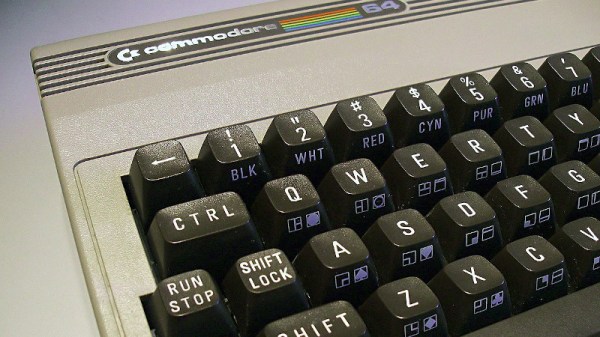
Older CPUs and some fairly modern microcontrollers are not made to readily support C compilers. Among those are the 1802, some 8-bit PICs, and the 6502 at the heart of the Commodore 64. That’s not to say you can’t make a C compiler for any of them, but the tricks required to handle the odd word sizes, lack of stack manipulation, or whatever other reason C isn’t a good fit tends to make compiled code bloated and possibly slower. [Dr. Mortal Wombat] took a different approach. The oscar64 compiler takes C source code and compiles it to a virtual machine code or native machine code for cases where performance might be important.
Turns out, the penalty for using native code isn’t as much as predicted, at least in some cases, The performance penalty for using the interpreter, however, can be significant in many common cases. The 6502 has a small stack that is hard to address, and indexing into a user-maintained stack is slow. The word size problem also produces lots of code as you have to break 16-bit operations into multiple 8-bit ones. The compiler aims to be C99-compliant, including floating point, recursion, multiple dimensions for arrays, and pointers to structures.
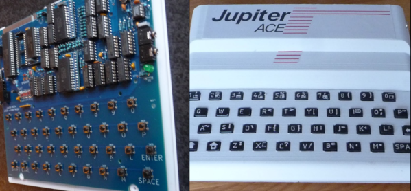
There are a few things left to hammer out. The linker doesn’t support external libraries, and the floating point code doesn’t understand NaN. On the other hand, many C++ features are available, like namespaces, reference types, templates, and more. The compiler can target several Commodore machines from the C128 to the PET. It also works with some Nintendo and Atari systems and can create various cartridge formats.
If you are writing code for any kind of 6502, it is probably worth checking out. Compiling C for the 6502 is no small feat, but then, so it is targeting PowerPoint. Don’t have a C64? Build one.
Image: [MOS6502], CC-BY-SA 3.0