Photoplotting PCBs With A 3D Printer

Do you ever wonder why your PCB maker uses Gerber files? It doesn’t have to do with baby food. Gerber was the company that introduced photoplotting. Early machines used a xenon bulb to project shapes from an aperture to plot on a piece of film. You can then use that film for photolithography which has a lot of uses, including making printed circuit boards. [Wil Straver] decided to make his own photoplotter using a 3D printer in two dimensions and a UV LED. You can see the results in the video below.

A small 3D printed assembly holds a circuit board, the LED, and a magnet to hold it all to the 3D printer. Of course, an LED is a big large for a PCB trace, so he creates a 0.3 mm aperture by printing a mold and using it to cast epoxy to make the part that contacts the PCB film.

Continue reading “Photoplotting PCBs With A 3D Printer”

String Operations The Hard(ware) Way

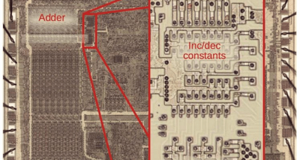
One of the interesting features of the 8086 back in 1978 was the provision for “string” instructions. These took the form of prefixes that would repeat the next instruction a certain number of times. The next instruction was meant to be one of a few string instructions that operated on memory regions and updated pointers to the memory region with each repeated operation. [Ken Shirriff] examines the 8086 die up close and personal to explain how the 8086 microcode pulled this off and it is a great read, as usual.

In general, the string instructions wanted memory pointers in the SI and DI registers and a count in CX. The flags also have a direction bit that determines if the SI and DI registers will increase or decrease on each execution. The repeat prefix could also have conditions on it. In other words, a REP prefix will execute the following string instruction until CX is zero. The REPZ and REPNZ prefixes would do the same but also stop early if the zero flag was set (REPZ) or not set (REPNZ) after each operation. The instructions can work on 8-bit data or 16-bit data and oddly, as [Ken] points out — the microcode is the same either way.

[Ken] does a great job of explaining it all, so we won’t try to repeat it here. But it is more complicated than you’d initially expect. Partially this is because the instruction can be interrupted after any operation. Also, changing the SI and DI registers not only have to account for increment or decrement, but also needs to understand the byte or word size in play. Worse still, an unaligned word had to be broken up into two different accesses. A lot of logic to put in a relatively small amount of silicon.

Even if you never design a microcoded CPU, the discussion is fascinating, and the microphotography is fun to look at, too. We always enjoy [Ken’s] posts on little CPUs and big computers.

Building The OhSillyScope

If you have a Raspberry Pi connected to an LED matrix, you might think about creating a simple oscilloscope. Of course, the Pi isn’t really well-suited for that and neither is an LED matrix, so [Thomas McDonald] decided to create the OhSillyScope, instead.

The device isn’t very practical, but it does add some flash to live music performances or it makes a cool music visualizer. The matrix is only 64×64 so you can’t really expect it to match a proper scope. Besides that, it pulls its data from the Pi’s ALSA sound system.

You can find a video of the device on [Thomas’] Reddit post and a few additional videos on his Instagram account. Looks like a fun project and it also serves as a nice example if you need to read data from the sound card or drive that particular LED matrix.

We might have opted for PortAudio if we had written the same code, but only because it is more portable, which probably doesn’t matter here. Of course, you could also use GNURadio and some Python to drive the display. As usual, plenty of ways to solve any given problem.

Fast Scanning Bed Leveling

The bane of 3D printing is what people commonly call bed leveling. The name is a bit of a misnomer since you aren’t actually getting the bed level but making the bed and the print head parallel. Many modern printers probe the bed at different points using their own nozzle, a contact probe, or a non-contact probe and develop a model of where the bed is at various points. It then moves the head up and down to maintain a constant distance between the head and the bed, so you don’t have to fix any irregularities. [YGK3D] shows off the Beacon surface scanner, which is technically a non-contact probe, to do this, but it is very different from the normal inductive or capacitive probes, as you can see in the video below. Unfortunately, we didn’t get to see it print because [YGK3D] mounted it too low to get the nozzle down on the bed. However, it did scan the bed, and you can learn a lot about how the device works in the video. If you want to see one actually printing, watch the second, very purple video from [Dre Duvenage].

Generally, the issues with probes are making them repeatable, able to sense the bed, and the speed of probing all the points on the bed. If your bed is relatively flat, you might get away with probing only 3 points so you can understand how the bed is tilted. That won’t help you if your bed has bumps and valleys or even just twists in it. So most people will probe a grid of points.

Continue reading “Fast Scanning Bed Leveling”

Retrotechtacular: Voice Controlled Typewriter Science Project In 1958

Hackaday readers might know [Victor Scheinman] as the pioneer who built some of the first practical robot arms. But what was a kid like that doing in high school? Thanks to a film about the 1958 New York City Science Fair, we know he was building a voice-activated typewriter. Don’t believe it? Watch it yourself below, thanks to [David Hoffman].

Ok, we know. Voice typing is no big deal today, and, frankly, [Victor’s] attempt isn’t going to amaze anyone today. But think about it. It was 1958! All those boat anchor ham radios behind him aren’t antiques. That’s what radios looked like in 1958. Plus, the kid is 16 years old. We’d say he did pretty darn good!

Continue reading “Retrotechtacular: Voice Controlled Typewriter Science Project In 1958”

Finding Paths With Water Is A-Mazing

We aren’t sure if it qualifies as fluidic logic, but [Steve Mould] was inspired by a simulation of water flowing through a maze and decided to build some actual mazes and watch water flowing through them. It turns out there are several physical effects in play, and you can see [Steve] discuss them in the video below.

The maze, of course, has to be oriented so that water flows into the top and flows out of the bottom. Without much thought, you’d think that the water just goes to the bottom and then fills up. Eventually, the part that is open at the bottom will have water coming out, right? Turns out it isn’t that simple.

A combination of air pressure and surface tension conspire to make the water do better than expected. Not that it perfectly solves it, but it doesn’t just fill up the entire maze, either. Even more interesting is that once the water has found the bottom, changing the water color will clearly show the path through the maze since nearly all of the new colored water will follow the flow path.

Practical? We can’t think of why. But it is a great think piece on how water flows and what sort of forces can affect it.

[Steve] is no stranger to making water work out algorithms, something called fluidic logic.

Continue reading “Finding Paths With Water Is A-Mazing”

Retrotechtacular: Solder Like Its 1944!

When we first saw this 1944 US Office of Education film about hand soldering, we figured it might still have some good information. Well, perhaps it does, but the 1944 soldering was with a giant iron, and the work looked more like metal bricks than anything we’ve soldered lately. Of course, the physics is all the same, but some of the terminology, like “sweating in” isn’t anything we’ve heard before, although we have heard of sweat soldering.

They do show some electronic soldering on components, including some interesting-looking coils. But the irons look more like a bad science fiction movie’s idea of a lightsaber. The solder is equally huge, of course.

Continue reading “Retrotechtacular: Solder Like Its 1944!”