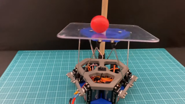
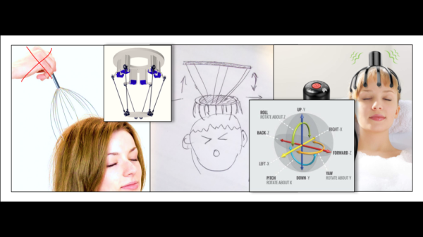
Stewy is a very interesting robot, with some slightly odd kinematics. Its head is a Stewart platform, which is a common-enough 6-DOF actuated plate normally used with a fixed base. By connecting legs to the same servos running the Stewart platform, [JD] turned it into an adorable hexapod walker. The walker had a problem, though: it can’t feel its feet, and [JD] thinks that would make it much more mobile on uneven surfaces. So he got some resistors to turn the cheap servos in its legs into force-sensing actuators.
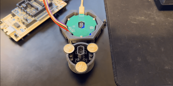
Well, almost. He’s not actually putting strain gauges or anything like that into the legs; he’s just measuring the voltage drop across a resistor in series with the servos. Since the motors draw more current the more torque they’re putting out, he has a very quick and easy way to sense the current and thus the torque using good old Ohm’s law and an analog input on the microcontroller driving the robot. It’s a simple hack, but the data he’s getting is surprisingly good for how much work it is to add to a robot, as you can see in the video — at least once he slowed down the servos a touch.
Perhaps this isn’t a ground-breaking innovation, but [JD] does a very good idea explaining it. Of course if you want to use resistors to sense force directly, force-sensitive resistors are a thing that we’ve seen in everything from Twister-mat MIDI controllers to self-leveling 3D printers.
Continue reading “Stewart Platform Walker Gains Feeling In Legs From Resistors”
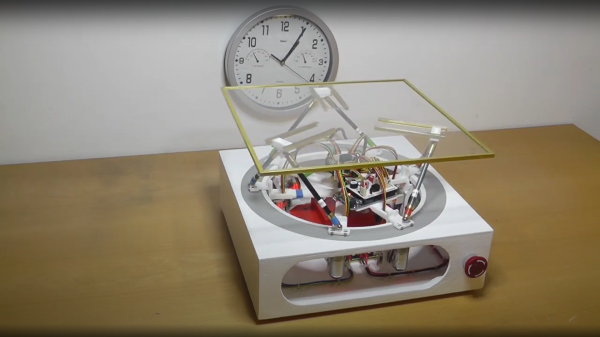
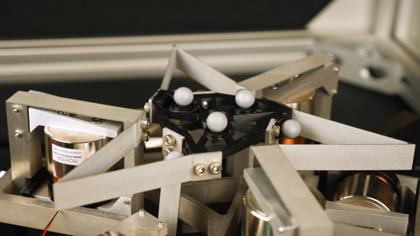
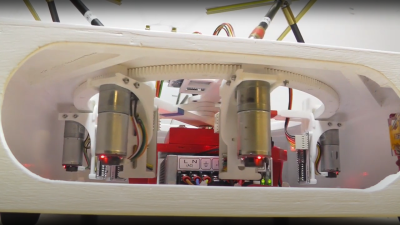 series of videos from a few years ago, showing the construction and operation of such a beast. This is a very neat mechanism comprised of six geared motors on the end of arms, engaging with a large internal gear. The common end of each arm rides on the central shaft, each with its own bearing. With the addition of the usual six linkages, twelve ball joints, and a few brackets, a complete platform is realised.