[Ctrl-Alt-Rees] bought something strange on an auction site: a Japanese Cefucom-21 from 1983. No? Didn’t ring a bell for us either. The legend on the front boldly proclaims: “CCI Multipurpose SLAP Computer,” so maybe it is some kind of computer, but it is definitely strange. For one thing, the “screen” isn’t a screen at all. [Rees] has found that it has something to do with teaching English. You can see the odd beast in the video below.
We don’t know how common these were in Japan, but they appear to be virtually unknown everywhere else. Inside is a Z80 computer based on a Sanyo PHC-25, which is a little better known.
Generally speaking, the Hackaday Supercon badge will always have a place for SAO (rebranded as “Supercon add-ons”), and that makes sense. We did originate them, after all. This year, though, we’ve gone all in on SAO, and, in particular, we’ve asked to see more SAOs with communication capabilities. The standard has always had an I2C bus, but few people use them. I decided I wanted to set an example and cook up a badge for Supercon. Was it hard? Yes and no. I’ll share with you a little about the board’s genesis and the issues I found. At the end, I’ll make you a special offer, if you are going to Supercon.
The Idea
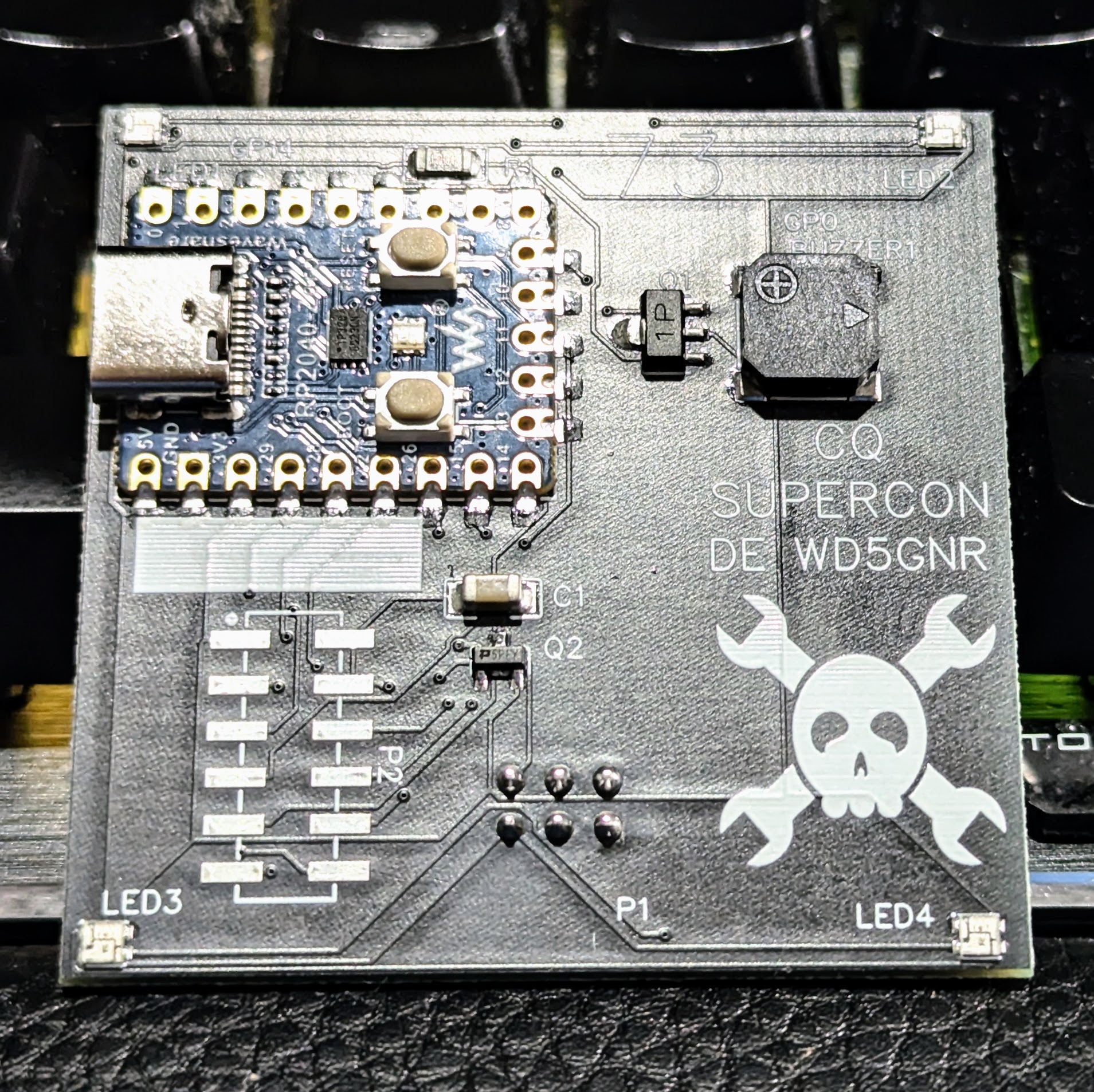
The front of the SAOGNR — the SAO connector is, of course, on the back
I’ve been a ham radio operator for a very long time. In fact, July was my 47th anniversary in the radio hobby. Well, that’s not true. It was my 47th year with a license. I had been listening to shortwave long before then. So, I wanted to do something with Morse code. You don’t have to know Morse code to get a license these days, but a lot of hams enjoy it.
I set out to do a simple board that would play some Morse code messages. But that’s just another blinking light LED with a buzzer on it, too. So, naturally, I decided it would also provide Morse code output for the I2C host. That is, the SAO could be used to convert ASCII to Morse code. Sounds simple, right? Sure.
Getting Started
I wanted to use a Raspberry Pi Pico but didn’t want to violate the SAO size requirements. Luckily, there’s an RP2040-Zero module that is quite tiny and looks more or less like a normal Pico. The two big differences are plusses: they have a reset button, and instead of a normal LED, they have a WS2812b-style LED.
[Igor] has an AS5600 magnetic rotary encoder chip on a breakout board. Normally, you’d think that was an easy device to work with since it has an I2C interface. But [Igor] wanted to do it the hard way. What’s the hard way? By hand. He directly manipulates the clock and data lines using some push buttons. You can see how it goes in the video below.
This is possible because the controlling device — in this case [Igor] — gets to set the clock rate, and there’s no reason it has to be regular. We have to admit that it never occurred to us to do this, but we have written “bit banged” I2C-like code before.
[Julian] knows that real diodes you can buy don’t work exactly like we say they do. That’s actually pretty common. We routinely ignore things like wire resistance and source resistance in batteries. Diodes have problems that are harder to ignore, such as the forward voltage drop. So, while a real diode will only pass current in one direction, it will also drop some of the voltage. [Julian] shows you how you can get simulated ideal diodes and why you might want them in a recent video you can see below.
The video starts with a simple demonstration and enumerates some of the practical limitations. Then, he pulls out some ideal diode modules. These typically don’t solve every problem, so they aren’t really ideal in the theoretical sense. But they typically appear to have no forward voltage drop.
If you are younger than a certain age, RLL probably doesn’t mean much to you. Old consumer-grade hard drives used MFM (modified frequency modulation like a floppy disk uses) and soon went to IDE (integrated drive electronics). There was a brief period when RLL (run length limited) drives were the way to get a little more life out of the MFM technology. [W1ngsfly] has an RLL drive on his bench and uses his scope and some other gear to put it through its paces. You can watch over his shoulder in the video below.
The hardware interface and drive are the same for an MFM and an RLL drive. However, an RLL-aware controller can pack more bits on the same platter by using the newer modulation scheme. Some older disks were good enough for MFM but too sloppy to successfully take an RLL format, but — in theory — any MFM drive could be an RLL drive and vice versa.
We’ve often heard you should do everything twice. The first time is to learn what you need to do, and the second time is to do it right. We bet [Ian Carey] would agree after taking his old linear power supply PCB and changing it to a switching regulator design. You can see more about the project in the video below.
The first power-up revealed a problem with the 3.3V output. We’ve often thought it is harder to troubleshoot a new design than it is to repair something that is known to have worked at one time.
You normally think of smart glasses as something you wear as either an accessory or, if you need a little assistance, with corrective lenses. But [akhilnagori] has a different kind of smart eyewear. These glasses scan and read text in the user’s ear.
This project was inspired by a blind child who enjoyed listening to stories but could not read beyond a few braille books. The glasses perform the reading using a Raspberry Pi Zero 2 W and a machine learning algorithm.