![]()
Here’s a quick tip to extend the usefulness of your multimeter. It’s a set of mini test hooks soldered to alligator clips with a short hunk of stranded wire in between. You can buy mini test hooks that go right on the metal probes of your meter, but the weight and bulk of the meter probes and cords sometimes get in the way. This rig allows more flexibility because of that wire.
Staying on the theme of test equipment tips, here’s a simple way to make a Y-connector for logic analyzers. [Thomas] uses a dual-row pin header, shorting each pair of pins so that both rows are connected. When this is plugged into a pin socket it leave two pins for connecting your test equipment and the rest of the project hardware.
After seeing our feature of a 3-wire Character LCD [Chad] wrote in to mention he built a 1-wire version using an ATmega328.
If you’re going to be in Anaheim this week you can stop by the ATX-West expo and see a 3D printer with a 1m x 1m x 0.5m printing area. [Thanks Martin]
Speaking of 3D printers, here’s a big delta robot (seven feet tall) outfitted for alternative material printing. It’s printing a CT scan of ribs and a heart in hot glue. This seems to be a popular material for more artistic uses. We just saw a hexapod which deposits hot glue as it roams.
The weaponized quadcopter post from Tuesday was a controversial one. The really bad part of it was the laser, which strapped to anything is extremely dangerous. But the other hack may have just been poorly executed. Hackaday alum [Jeremy Cook] wrote in to mention that fireworks and quadcopters can be used more responsibly. He strapped a sparkler to his quadro and used it to make light graffiti. You may remember that [Jeremy] wrote an introduction to light graffiti for us back in November.
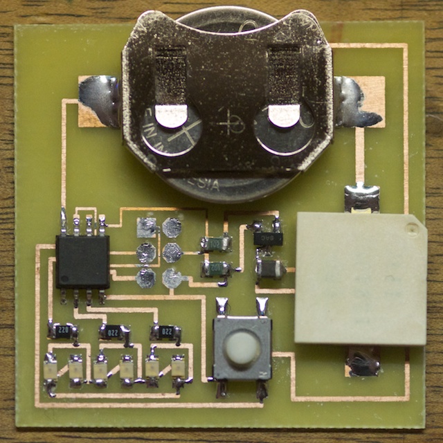 Do you want to use your time more productively but are tomato-averse? [Robin]’s