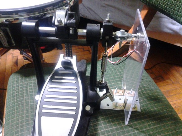
DCF77 Signal Filtering And Decoding

dcf77-filtering-and-decoding

[Udo] decided to build a clock using the DCF77 radio module seen above. This of course has been done before: the hardware draws a clock signal from the atomic clock in Braunschweig, Germany. So he grabbed a library for Arduino and got to work. But he was getting rather poor results and upon further investigation realized that the library had been written for 20 Hz modules and his operates at 300 Hz. This means better accuracy but the drawback is that the hardware is more susceptible to noise.

So began his journey to filter, process, and decode the DCF77 protocol. That link goes to the project overview. It will be in several parts all of which will be linked on that page. So far he has applied a low-pass filter and coded some exponential smoothing. He has yet to write the other four parts, but does mention that early testing shows that this technique will make the reception better than what is achieved with commercially available clocks. He was able to lock onto a signal that had more than 80% noise ratio. That’s impressive!

Just want to see a clock that uses a DCF77 module? Check out this PIC-based atomic clock.

Clock Display Taller Than You Is Just What Your Living Room Has Been Missing

huge-countdown-clock

Sure, it’s time to get the countdown clocks ready to ring in the new year, but why limit it to just one night? If you end up building a six-foot digital display you can count down trivial events; like the remaining seconds of freedom before you have to pimp yourself out in that drab cubicle.

This seven-segment display is homemade and boasts six full-sized digits and two smaller digits with each pair separated by colons. You have probably already guessed that the construction was greatly simplified by using LED strips rather than individual components. This is part of the reason for the size of the display. The strips can be cut, but only down to a minimum of 3 LEDs per segment. That explains the small digits, with their larger siblings doubled in size. But there is a benefit to this constraint, it means that current limiting is already taken care of for you.

The main assembly is a wooden frame surrounding two polycarbonate sheets. The LED strips are sandwiched between those sheets, with segment and digit driver buses exiting a one point on the side. The build doesn’t detail a driver for the display but it shouldn’t be hard to find a multiplexing example that will serve the purpose.

A Study Of GCC And The TI Stellaris

hard-look-at-stellaris-and-gcc

There are several things that we really like about the TI Stellaris. We think the peripheral library — called Stellarisware — has a pretty intuitive API that makes it easy to get into. But we’re also quite impressed that the software comes with makefiles that build the libraries and examples using your own GCC cross compiling toolchain. We spent quite a bit of time pawing through those makefiles and the makedefs settings file to figure out how TI was doing things. Now if you don’t want to do that sleuthing yourself you can head on over to the GCC with TI Stellaris Launchpad guide which [Brandon] just published.

Shown above is the helpful chart of compiler flags which he pulled from the files with his added comments on what each does. He did the same for the linker flags, and then discusses the program calls made during compilation and linking. He then delves into how the driver library on the chip’s ROM can be accessed in code. This is just the first in a four-part series he plans to write. We can’t wait to see what he has to say about the hardware FPU as we haven’t had time to explore that for ourselves quite yet.

RS-485 Node Control For Arduino

rs-485-arduino-nodes

Wanting to control a split flap display that was not near a computer [Tom] looked to a common solution for communicating over distances not practical for I2C or SPI. He developed his own hardware and packet format using the RS-485 protocol.

This is part of a larger project he has been working on to feed data to a split flap display that he plans to hang on the wall. RS-485 is designed to work over long distances and overcome noise issues. The core of the communications system is the board seen on the left. It uses a MAX1483 chip, a pair of RJ45 jacks for Ethernet cables, and two terminal blocks for power and communications. There are a few nice things about this. The board acts as a pass-through making it easy to chain nodes together, and the data structure is completely independent of the hardware itself. Because of this [Tom] developed his own packet format that will be a bit more resilient than the Arduino networking scheme we looked at the other day.

Syncing Two Strands Of G35 Christmas Lights

Lights

For a few years now, the set of Christmas lights most wanted by hackers and makers the world over is the GE G35 color changing set. With 50 individual RGB LEDs controlled by a microcontroller, these light strings can display any pattern of lights with the help of something as simple as an Arduino. The stock light sequences are a little problematic, especially if you’re running more than one string.

[Todd] picked up two G35 strings, and even when they’re turned on at the same time the light sequences slowly go out of sync after a half hour or so. He came up with a great way to make sure these lights stay in sync that requires only a slight modification. To make two light strings stay in sync, it’s simply a matter of disconnecting the data line from one string’s controllers and bridging that connection with the other string.

It’s a very easy modification, but it won’t give you twice as many individually controllable LEDs – for that, you’ll have to use either multiple Arduinos or buy a longer RGB LED strip. Still, having two identical 7×7 LED panels is better than a single panel, so we’ll have to tip our hat to [Todd] for this one.

Cute Little Amplifier Has A Tube Pre

tube

While you won’t catch us in an argument with an audiophile regarding the sound quality of tube vs. solid state amps, there is a general consensus that tube amplifiers sound much better than their transistorized brethren. Actually building an all-tube amplifier, though, is a bit harder than one built around common ICs – there are transformers to deal with and of course very high voltages. One solution to get the sound of tubes easily but still retaining the simplicity of integrated circuits is a hybrid amp, or a tube preamplifier combined with a solid state power section. They’re easy enough to build as [Danilo] shows us with his hybrid tube amp design (Italian, translation).

[Danilo]’s design uses two ECC86 for the left and right channels powered by a 12 Volt supply. Each channel is sent through a tube and then amplified by a TDA2005 20 Watt power amplifier. After plugging in a CD player, the result is a clear, warm sound that can put a whole lot of power through a speaker.

Self Balancing Unicycle Built From Old Scooter

[Glenn] had an old electric scooter/motorcycle in his garage that had long ago given up the ghost. Without a working battery and motor controller this scooter wasn’t beyond repair, but [Glenn] thought he could use it to build something much, much cooler. What he came up with is a self-balancing unicycle that borrows inspiration from a Segway and other self-balancing robots.

After cutting the drive chain off his scooter, [Glenn] began work on installing a new motor controller and battery. To make this unicycle balance itself, he would need a few gyroscopes and accelerometers provided via an Arduino and Sparkfun IMU shield.

After tuning his PID loop, [Glenn] hopped on his new ride and took it for a spin with the help of a pair of ski poles. It’s much easier to ride than a traditional unicycle and [Glenn] says he’s getting better at riding it.