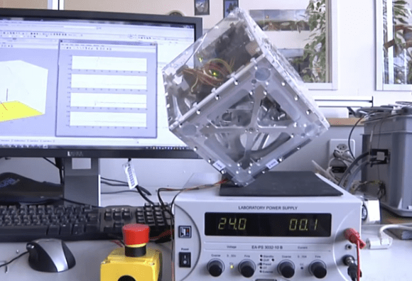
When [Andrei] first got his Raspberry Pi he wanted to make it a standalone computer right away. This means the normal input devices like a mouse and keyboard, but also some type of display. To avoid waiting for shipping he ended up using a cheap vehicle backup camera screen from the local big box store. It worked great, and recently he decided he would try to convert it to run off of 5V power to simplify his setup. While snooping around inside the device he discovered an unused resistive touch overlay and figured out how to get it to work.
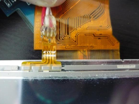
What tipped him off is the small four-conductor connector which wasn’t hooked up to anything. He carefully soldered wires onto the flexible circuit traces, then generously covered them in hot glue to help prevent movement from breaking the rigid connection. To get this working you need to measure the resistance between the conductors. Most of the time we figure the RPi GPIO header can be used directly, but for this task an intermediary is necessary. [Andrei] went with a small Arduino clone board. A bit of trial and error was all it took to get the connections right and to iron out the code which translates the values into coordinates.