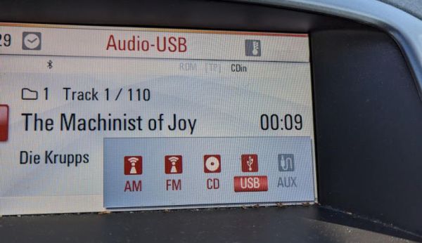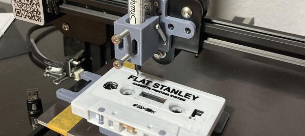
One way to look at FDM 3D printers is as machines that turn filament into three-dimensional objects, but at their core they are much more versatile than that. Since they can move just about any tool around in 3D space, you can also use them for plotter tasks, a fact that [Geoffrey Gao] made use of when he had to write labels for a stack of music tapes. The resulting FS-Plotter project is based around a Creality Ender 3 FDM printer. Standard g-code from PrusaSlicer is used to move a pen around, after the latter has been fitted into a (3D-printed) spring-loaded fixture.
The cassette tape is fitted into its own fixture that is attached to the printer bed to hold it in place, while the writing utensil can move in its spring-loaded fixture to account for some unevenness on the surface it’s writing on. In the linked GitHub project a PrusaSlicer profile is provided that can generate 2D plotter Gcode. Where [Geoffrey] says that this project is very useful to him as a musician is that it enables him to make small runs of tapes with professional printing, without running into extra expenses.
Beyond putting a writing utensil into the holder, it could also be used for light engraving and similar tasks, while still making it possible to switch between the FDM hotend and this plotter attachment as needed. For about $30 in parts, it doesn’t seem like a bad deal to get a small-ish plotter and maybe give that old Ender 3 a second life.
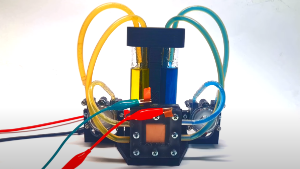
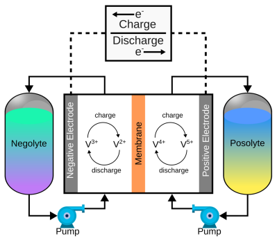 of a pair of electrolytes. These are held externally to the cell and connected with a pair of pumps. The capacity of a flow battery depends not upon the electrodes but instead the volume and concentration of the electrolyte, which means, for stationary installations, to increase storage, you need a bigger pair of tanks. There are even 4 MWh containerised flow batteries installed in various locations where the storage of renewable-derived energy needs a buffer to smooth out the power flow. The neat thing about vanadium flow batteries is centred around the versatility of vanadium itself. It can exist in four stable oxidation states so that a flow battery can utilise it for both sides of the reaction cell.