Truth be told, we haven’t jumped on the Wordle bandwagon yet, mainly because we don’t need to be provided with yet another diversion — we’re more than capable of finding our own rabbit holes to fall down, thank you very much. But the word puzzle does look intriguing, and since the rules and the interface are pretty simple, it’s no wonder we’ve seen a few efforts like this automated Wordle solver crop up lately.
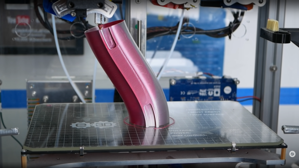
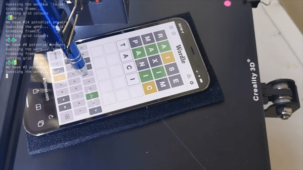
The goal of Wordle is to find a specific five-letter, more-or-less-common English word in as few guesses as possible. Clues are given at each turn in the form of color-coding the letters to indicate whether they appear in the word and in what order. [iamflimflam1]’s approach was to attach a Raspberry Pi camera over the bed of a 3D printer and attach a phone stylus in place of the print head. A phone running Wordle is placed on the printer bed, and Open CV is used to find both the screen of the phone, as well as the position of the phone on the printer bed. From there, the robot uses the stylus to enter an opening word, analyzes the colors of the boxes, and narrows in on a solution.
The video below shows the bot in use, and source code is available if you want to try it yourself. If you need a deeper dive into Wordle solving algorithms, and indeed other variant puzzles in the *dle space, check out this recent article on reverse engineering the popular game.
Continue reading “Solving Wordle By Adding Machine Vision To A 3D Printer”