Arduino Nano Floppy Emulator For When Your Disk Is Not Accessible

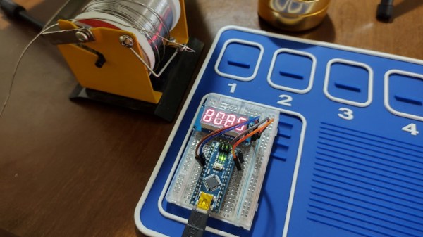
Among the plethora of obsolete removable media there are some which are lamented, but it can be difficult to find those who regret the passing of the floppy disk. These flexible magnetic disks in hard plastic covers were a staple of computing until some time in the early 2000s, and their drives could be found by the crateload in any spares box. But what about today, when there’s a need for a real floppy drive and none is to be found? Enter [Acemi Elektronikci], with an Arduino Nano based floppy emulator, that plugs into the floppy port of a PC old enough to have one, and allows the easy use of virtual floppy disks.

Aside from the Nano it has an SD card and associated level shifter, and an SSD1306 i2c screen. Most of the Arduino’s lines drive the floppy interface, so the five-button control comes to a single ADC pin via a resistor ladder. He freely admits that it’s not a perfect cycle-exact emulator of original hardware and there may be machines or even operating systems that complain when faced with it, but for all that it is a useful tool. One of the machines that may have issues is the Amiga, but fortunately there’s a fix for that with a Raspberry Pi.

A tiny TV that shows weather, news, and the classic test pattern.

Tiny TV Tells The Temperature Tale

Once upon a time, we would run home from the bus stop to watch Gargoyles and Brady Bunch reruns on the family TV, a late-1970s console Magnavox number that sat on the floor and was about 50% more cabinet than CRT. The old TV, a streamlined white Zenith at least ten years older, had been relegated to the man cave in the basement. It looked so mod compared to the “new” TV, but that’s not the aesthetic my folks were after. They wanted their electronics to double as furniture.

This little TV is a happy medium between the two styles, and for us, it’s all about those feet. But instead of cartoons, it switches between showing the current weather and the top news headlines. Inside that classy oak cabinet is an LCD, an ESP32, and an SD card module. The TV uses OpenWeatherMap and pulls the corresponding weather image from the SD card based on time of day — light images for day, and dark images for night.

We love that it shows the SMPTE color bars, aka the standard American TV test pattern as it switches between weather and news. After showing the top headlines, it automatically switches back to the weather channel. Be sure to check out the short demo video after the break.

Do you like your tiny televisions in strange places? Here’s one you can use to trim your tree this year.

Continue reading “Tiny TV Tells The Temperature Tale”

Arduino Becomes Superhet With A Little Help From Friends

A radio receiver is always a fun project. [Jayakody2000lk] decided that his new superheterodyne design would use an Arduino and it looks like it came out very nicely. The system has four boards. An off-the-shelf Arduino, a Si5351 clock generator board (also off-the-shelf), and two custom boards that contain the IF amplifier and mixer.

The receiver started out in 2015 without the Arduino, and there’s a link in the post to that original design. Using the Si5351 and the Arduino replaces the original local oscillator and there have been other improvements, as well. You can see a video about the receiver below.

Tuning is by a rotary encoder and the current software lets you tune from about 4.75 MHz to a little over 15.8 MHz. Of course, you could change to any frequency the Si5351 can handle as long as the mixer and other components can handle it. The IF frequency is the usual 455 kHz.

If you decide to build this yourself, the design files are on GitHub. Overall a very nice and neat design. We are always amazed how little radio architecture has changed since Edwin Armstrong’s day. Of course, we have better components, even if they aren’t meant for radio purposes.

Continue reading “Arduino Becomes Superhet With A Little Help From Friends”

Dial A For Arduino

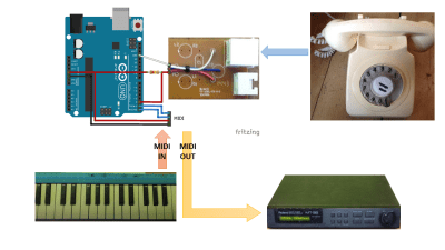
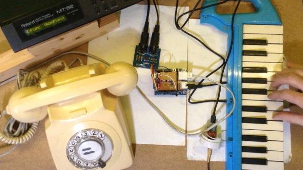
A lot of phrases surrounding phones don’t make sense anymore. With a modern cellphone, you don’t really “hang up” and there’s certainly no “dial” to be had. However, with [jakeofalltrades’] project, you can read an old-fashioned phone dial using an Arduino.

The idea behind a phone dial is actually pretty simple. When you pull the dial back to the stop using one of the numbered holes and release it, it causes a switch to open and close the same number of times as the hole you selected. That is, if you pull back the 5 hole, you should get 5 switch closures. The duration of each switch event and the time between switch events is a function of the speed the dial moves because of its internal spring. The zero hole actually produces ten pulses.

There are standards for how precise the timing has to be, but — honestly — it’s pretty loose since these were not made to be read by precise microcontroller timers. In the United States, for example, the dial was supposed to produce between 9.5 and 10.5 pulses per second, but the equipment on the other end would tolerate anything from 8 to 11.

Even if you don’t want a rotary dial in your next project, the code has some good examples of using ATmega328 timers that you might find useful in another context. However, a dial would add a nice retro touch to any numeric input you might happen to need.

If you need project inspiration, how about a volume control? Or, why not a numeric keypad?

A French Minitel terminal becomes a Raspberry Pi-powered mini laptop.

Minitel Terminal Becomes Mini Laptop

In 1980, France took a step into the future when the telecom companies introduced the Minitel system — a precursor to the Web where users could shop, buy train tickets, check stocks, and send and receive electronic mail through a small terminal. Minitel still had 10 million monthly connections in 2009, but the service was discontinued in 2012.

The keyboard of a French Minitel terminal is wired up to an Arduino Pro Micro.So, you can imagine how many Minitel terminals must be floating around at this point. [Gautchh] picked one up at a garage sale a while back and converted it into a battery-powered laptop for taking notes in class. Luckily for us, [Gautchh] recently open-sourced this project and has given us a wiring diagram, STLs, BOM, and a good look into the build process.

[Gautchh] started by gutting the Minitel, but saved the power button and the très chic power indicator that looks like a AA cell. The new 10.4″ LCD screen is held in place with four 3D-printed corner blocks and a bit of hot glue, and the original keyboard (which we’d love to clack on) is now wired up to an Arduino Pro Micro. The main brain — a Raspberry Pi 3B — is easily accessible through a handy little hatch in the back. Well, it looks like we’ve got a new ebay alert to set up.

In the mood for more AZERTY goodness? Check out this gallery of French computers, or a more traditional take on a Minitel with a Raspberry Pi.

LED Matrix Hourglass Knows Which Way Is Up

[Fearless Night]’s slick dual hourglass doesn’t just simulate sand with LEDs, it also emulates the effects of gravity on those simulated particles and offers a few different mode options.

The unit uses an Arduino (with ATMEGA328P) and an MPU-6050 accelerometer breakout board to sense orientation and movement, and the rest is just a matter of software. Both the Arduino and the MPU-6050 board are readily available and not particularly expensive, and the LED matrix displays are just 8×8 arrays of red/green LEDs, each driven by a HT16K33 LED controller IC.

The enclosure and stand are both 3D-printed, and a PCB not only mounts the components but also serves as a top cover, with the silkscreen layer of the PCB making for some handy labels. It’s a clever way to make the PCB pull double-duty, which is a technique [Fearless Night] also used on their earlier optical theremin design.

Those looking to make one of their own will find all the design files and source code handily available from the project page. It might not be able to tell time in the classical sense, but seeing the hourglass displays react to the device’s orientation is a really neat effect.

World’s Cheapest And Possibly Worst IR Camera

Don’t blame us for the title. [CCrome] admits it may well be the cheapest and worst IR camera available. The concept is surprisingly simple. Mount a cheap Harbor Freight non-contact thermometer on a 3D printer carriage and use it to scan the target. The design files are available on GitHub.

There is, of course, an Arduino to grab the data and send it to the PC. Some Python code takes care of converting it into an image.

Perhaps you don’t need a camera, but having a way to communicate with an $11 IR temperature sensor might come in handy someday. You do have to mash the measurement button down, so [CCrome] used the 3D printer to make a clamp for the button that also holds the POGO pins to the PCB. We would have been tempted to solder across the switch and also solder the wires to the pad. But, then again, you need a 3D printer for the project anyway.

Don’t expect the results you would get from a real thermal sensor. If you want that, you may have to build it yourself or open your wallet wide. If you need some inspiration for a use case, look at the thermal camera contest from a few years back.