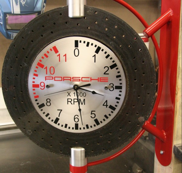
With an extra Porsche brake rotor lying about and a persistent friend to be silenced, [GordsGarage] decided to fabricate a one-of-a-kind man cave wall clock.
This was not to be a boring old hang-it-flat-on-the-wall design, though. The Porsche rotor is a composite design, with a steel hub and a ceramic disc weighing only a third of what an all-steel rotor weighs. That inspired [GordsGarage] to fabricate a wall bracket to hold the rotor and allow it to spin, showing off both sides. The business side has a brushed aluminum clock face with decals cut with a s vinyl-plotter and designed to look like a Porsche tachometer, while the reverse side has a nice custom badge for his friend’s shop. The build log shares some of the nice touches that went into the clock, like powder coated parts to mimic stock Porsche red brake calipers, and the secret [GordsGarage] logo.
It may not have been a clock for social good, but it’s a great design and a nice build that’s sure to brighten up his friend’s shop. And mancave warming presents are apparently a thing now, so we’ll be sure to keep our finger on the pulse of this social trend.

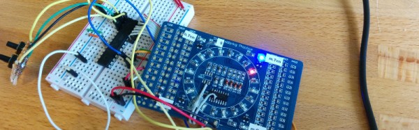


 The easy part consists of Neopixels, an Arduino Nano and a DS3231 Real Time Clock. The hard part consists of Plasticard and a polymorph diffuser. Plasticard also goes by the name of Polystyrene and comes in sheets. [David] describes Polymorph as a type of moldable nylon that softens with heat, with a working temperature low enough that boiling water will suffice.


