Making Better CNC Halftone Pictures

[Jason] was messing around with CNC machines and came up with his own halftone CNC picture that might be an improvement over previous attempts we’ve seen.

[Jason] was inspired by this Hack a Day post that converted a image halftone like the default Photoshop plugin or the rasterbator. The results were very nice, but once a user on the JoesCNC forum asked how he could make these ‘Mirage’ CNC picture panels, [Jason] knew what he had to do.

He immediately recognized the algorithm that generated the Mirage panels as based on the Gray-Scott reaction-diffusion algorithm. With this algorithm, dark areas look a little like fingerprints, meaning the toolhead of the CNC router can cut on the X and Y axes instead of a simple hole pattern with a traditional halftone. After a little bit of coding, [Jason] had an app that converted an image to a reaction-diffusion halftone which can then be converted to vectors and sent to a router.

It’s a very neat build and we imagine that [Jason]’s pictures would cost a bit less than the commercial panels. Check out the video after the break to see the fabrication process.

Continue reading “Making Better CNC Halftone Pictures”

A Laser Cutter Challenge

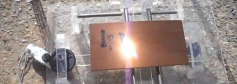
When the Louisville hackerspace LVL1 was discussing the purchase of a new laser cutter, a member said, “I could build one before you get around to buying one.”  The gauntlet was thrown down, a challenge was set, and the race was on to build a tiny laser cutter before the hackerspace took delivery of their new laser cutter.

The mechanical aspect of the build is fairly simple. The X axis is simply a stepper motor, threaded rod and laser module mounted on a carriage. This carriage moves along the Y axis with the help of two stepper motors for either side. Everything was mounted on more perfboard than reason would suggest.

For the electronics of the project, three motor drivers were made with a few logic chips and the laser firing relay was stolen from test equipment developed for LVL1’s trans-Atlantic balloon build. Motor and laser control was handled by an Arduino to keep the build simple because the contest was over after the first laser was finished cutting a square.

LVL1 is now working on a second version of the winner of the laser cutter challenge. They’re planning on a touchscreen interface that will cut a plastic blank about the size of a credit card. We can’t wait to see the results of that build.

super_sized_3d_printer

Huge DIY 3D Printer Predictably Prints Huge 3D Items

Well, if we ever need something huge built on a RepRap, now we know who to call. [Jim] over at Grass Roots Engineering wrote in to share a large 3D print he just finished, which was extruded by an equally impressive home-built 3D printer.

The part he built consists of a bunch of hollow green tubing in a criss-cross pattern and was printed in just under 2 days. He never mentions what the part is going to be used for, but at 376 x 376 x 250mm (14.8 x 14.8 x 9.84in), he estimates that this is the biggest single part printed with a DIY 3D printer.

The printer itself is based on the RepRap, but is obviously far larger. It prints using ABS plastic utilizing a maximum build area of 403 x 403 x 322.7mm (15.86 x 15.86 x 12.7in). Built over the course of 3 years, it was fully operational in 2010 but has undergone several improvements as [Jim’s] needs have changed.

It’s a fantastic looking machine, and it seems to print quite nicely. We would sure love to have one of these in our workshop.

Continue reading to see [Jim’s] 3D printer in action.

Continue reading “Huge DIY 3D Printer Predictably Prints Huge 3D Items”

Freakin’ Huge CNC Router

[Tom] sent in a gigantic 3-axis router that he pieced together during a 2 week-long work experience placement. Looking at this picture showing a 12-inch ruler on the work area, we realized that this may be the largest CNC router we’ve seen on Hack A Day.

[Tom]’s employer gave him some obsolete axes, so piecing the mechanical components together was very easy. The only real problem was interfacing the CNC controller to a computer. This meant [Tom] had to convert G Code to the code used by the antiquated NSK axes. Where G Code defines arcs with a start point, end point, and radius, the NSK code defines arcs with a start point, end point, and another point along the arc. It’s a tricky bit of math, but [Tom] built some software that did this in Visual Basic.

Right now, [Tom] only has a pen tool attached to the router; you can check that in action after the break. We’re trying to imagine what we would do with a 4 m² work area; this could easily be used to make a giant reprap or other 3D printer.

Continue reading “Freakin’ Huge CNC Router”

Delta Robot 3D Printer

Sometimes, not all our builds work out the way we hoped. That’s what happened to [Rob] and his attempt at a Delta robot that does stereo lithography. A Delta robot is capable of very fast and precise movements, so [Rob] slapped a laser module on the end of the arms. After putting some UV curing resin in front of the laser, he was left with a blob of goo and we’re trying to figure out why.

[Rob] thinks the admittedly terrible print quality was due to diffraction and the reflective build plate. If this were the case, we’d agree with the assessment that adding some dye to the resin would help. Some commentors on [Rob]’s blog have suggested that he’s running the laser too slowly. It’s a shame [Rob] scrapped his build and turned it into a plain-jane X & Y axis build. Delta robots can be really damn fast, and adding a printer to one might mean prints that take minutes instead of hours. There are a few people working to get a Delta RepRap off the ground, but this project still has another prototype or two before that happens. Check out [Rob]’s attempt at Delta robot stereolithography after the break.

Thanks to [techartisan] for sending this one in.

Continue reading “Delta Robot 3D Printer”

Building A CNC Router To Call My Own

As with most writers for [HAD], I enjoy doing projects as much as I like writing about them. As a mechanical Engineer that writes for a blog mostly about electronics, a CNC router seemed like something I needed in my garage. Building a router like this requires a bit of expertise in both electronics and mechanics, so it seemed like a good challenge.

This router kit, made by Zen Toolworks, comes fairly complete frame-wise, but requires a lot of knowledge on the electrical side to get things running correctly. In order to make it look decent and work correctly, I had to rely on some zip-tie and basic diagnostic skills that I’ve honed as a former engineering Co-op and technician. Also, I had to figure out a way to cheaply stack everything in my garage as we park two cars there (the footprint is 14″ x 22″, so I consider that a success).

One of the bigger challenges that I still have to overcome with this project is learning “G-code” and how to use software to generate it.  Although I’ve done some basic programming already, as seen in the video after the break, there’s still much to learn. I’d hope that having this tool around can lead to better projects as I won’t have to be restricted to simple milled lines and circles anymore.

Continue reading “Building A CNC Router To Call My Own”

Milling Curves Into Mirrors And Glass

[Ben Krasnow] is working on  a project that uses an extremely expensive specialty mirror. He needed to cut curves into it, taking care not to chip or shatter the material. He’s found a reliable way of doing this with a CNC mill and is sharing his methods.

The material he’s working with is a cold mirror; it reflects visible light while allowing infrared light to pass through. He had to custom order it, breakage is not acceptable. [Ben] explains that the biggest risk when milling glass is the clamping method used. He built his own jig and uses shims, rather than clamps, to secure the material along the X and Y axes. It is held down on the Z axis using a bar of acrylic spanning from one side to the other with rubber feet on the bottom.

A diamond burr cutter does the work, spinning at 3000 RPM. [Ben] recommends moving the head at the slowest rate possible in order to give the cutter time to do its work. And of course the material needs to be kept cool by pumping cutting fluid across it. As he shows in the video after the break, what you get is a piece of glass that comes out with clean and smooth edges.

In case we’ve sparked your curiosity, this mirror will be used during an MRI scan. The patient looks at a monitor reflected in the mirror at a 45 degree angle. At the same time, an infrared camera records the patient from the other side of the mirror to monitor where they are looking.

Continue reading “Milling Curves Into Mirrors And Glass”