Simple Solution Makes Rocket Fin Alignment A Breeze

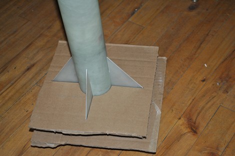
If you’re building model rockets you want to make sure they fly straight, and most of that is dependent on the stabilizer fins. It has long been a problem come assembly time. How can you make sure that they’re being aligned without any variation? [Rrix] mentioned that one technique is to use a square to position them perfectly perpendicular to the bench on which the rocket is being assembled. But this is still prone to error. His method uses a couple of precision jigs made out of cardboard.

He designed this pair of jigs in Inkscape, then used the files to fabricate them out on a laser cutter. It worked like a charm, but led him to another issue that can be solved in a similar way. Model rockets have rail guides that travel along a rod attached to the launch pad as the craft accelerates to a point where the fins have enough effect to keep it going in a straight line. If those guides aren’t straight, your fin alignment will be all for naught. His second version of the jigs includes a cut out for these guides.

Tearing Through Floppy Drives To Build A Small-format Dot Matrix Printer

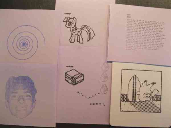
The accuracy which [Mario] achieved in his pen plotter dot matrix printer is very remarkable. He tore through a pile of floppy drives to get the parts he wanted, and chose to go with a fine-point Sharpie marker as a print head. In the video after the break he flatters us with a printout of the Hackaday logo, but you also get a look at one problem with the build. The ink doesn’t always flow from the felt tip and he has to coax it (almost like priming a pump) with a piece of scrap paper.

He was inspired by the pen printer we featured back in June. This rendition features a printing area of 1.5×1.5 inches that can accommodate 120×120 black and white pixels. He’s not a microcontroller type of guy and is driving the printer from the parallel port of his computer.

The best printing technique puts the pen down and moves it around just a bit (helps prevent the ink flow problem we mentioned earlier) and produces images like one in the lower right. We love the 8-bit nature of the result and would use this all the time to make our own greeting cards.

Continue reading “Tearing Through Floppy Drives To Build A Small-format Dot Matrix Printer”

3D DLP Printer Builds An Orange TARDIS

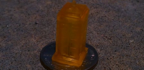
This micro-sized TARDIS is the latest print from [Ron Light]’s Sedgwick 3D DLP printer. Yes, it’s orange, but the print quality for such a small object is pretty astounding.

The Sedgwick 3D printer is currently available as a kit on Kickstarter. For five hundred bones, the Sedgwick provides all the parts – minus a DLP projector and resin – to make your own miniature Type 40 with a broken chameleon circuit. There’s a lot more this printer can do, from miniature cathedrals to hollow geodesic spheres.

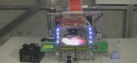
This is the latest in what will be a long line of DLP projector / resin 3D printers, and the most affordable one to date. The last one we saw was an awesome $2400 machine that included a projector and resin. At $500 for a projector-less kit, the Sedgwick still handily beats even the cheapest option we’ve seen so far.

[Ron Light] is from Kansas City, and our boss man [Caleb] ran into him at the KC Maker Faire a few weeks ago. You can check out that little interview and a few videos of the Sedgwick doing its thing after the break.

Continue reading “3D DLP Printer Builds An Orange TARDIS”

Easy To Build Parts Tumbler You Can Add To Your Shop

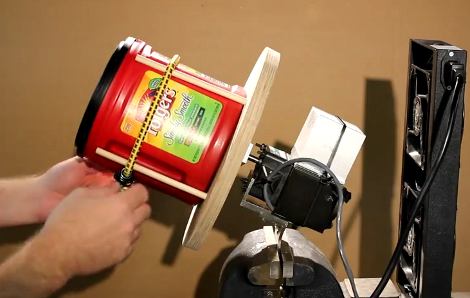
This parts tumbler was easy to build but it still does a great job of rounding rough edges and polishing the surfaces of parts cut with a CNC machine. You can see that it mounts in a bench vise, and the cooling fans have a magnet which holds the tray in place on the anvil portion of that tool. Since you’re not constantly tumbling parts this makes it very easy to store the unit between uses.

[Neo7CNC] mounted the wooden tumbler plate directly to the motor shaft. This is done with the help of some aluminum stock which bolts to the round wooden plate, and has a hole and set screw for the motor’s keyed shaft. There are four wooden dowels which cradle the plastic coffee jug where the parts go. As a first test he used zinc BB’s that he already had lying around, but has put some steel ball medium on order for future projects.

It’s certainly more robust and powerful than the LEGO ball mill we saw a while ago. Just be careful with motor. Even at a lowly 60 RPM it ended up getting really hot and that’s the reason there’s a heat sink and fan unit included in the build. See it in action after the break.

Continue reading “Easy To Build Parts Tumbler You Can Add To Your Shop”

CNC Table Saw Jig

table saw jig

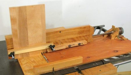
[Woodgears.ca] seems to be a wealth of clever hacks, and this CNC box joint jig is no exception.  Although one has to manually move the jig to make the actual cut, it still gives the user a lot of extra functionality. One only has to click the mouse button to advance the workpiece.  One drawback to using a table saw, even with this jig is that some internal parts still may have to be cut. Check out the video after the break to see this device in action, or skip to around 3:08 to see what hand operations still have to be done.

Besides just being a cool build, we loved the box-jointed project enclosure for the electronics. As this was made in 2003, it’s nice to see that the idea of “self-replication” (at least in part) didn’t start with the [Rep-Rap]. The 10 year old (as of 2003) Thinkpad notebook computer running QBasic in DOS is a nice “hacker” touch as is using 100 Watt light bulbs as power resistors. Pretty clever electronics, especially for someone that’s known more for his excellent woodworking skills than his obvious electrical engineering knowledge! Continue reading “CNC Table Saw Jig”

Printing Mounting Boards And Boxes For Hobby Projects

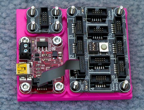
That’s a great base board for these Gadgeteer components. [Rob Miles] has been designing and printing mounting boards and enclosures for several of his projects. He just got into printing parts with the Ultimaker last week, and we’d say he’s found his stride. The board pictured here features nubs that act as stand-offs, and on the underside there are countersunk spaces for the bolt heads used as fasteners.

He started designing with Autodesk 123D but the interface didn’t really suit his working style. He switched over to FreeCAD and that experience fit him like a glove. He starts out with the sketch view to draw his parts, then extrudes that into the 3D model for further refinement before having the printer turn the digital into the real. This is the third board he produced in just one day of experimenting, but he is also showing off an enclosure he made for his thermal printer.

If you’re not working with boards that have nice mounting holes like these, don’t fret. We’ve seen 3d printed mounting systems that cradle the board, like these Raspberry Pi enclosures.

[Thanks Peter]

A Closer Looks Helps You Build Your Own DiWire Bender

Whether or not you’re actually going to build this CNC wire bender, we think you’ll love getting a closer look at how it’s put together. The team over at PENSA got such a strong response from a look at the original machine that they decided to film a video (embedded after the break) showing how the thing was put together. They’ve also posted a repository with code, bom, etc.

In the image above [Marco] shows off the portion that actually does the bending. It’s designed to mount on the pipe through which the straightened wire is fed. The 3d printed mounting bracket really makes this a lot easier. The assembly provides a place to attach the solenoid which moves a bearing in and out of position. That bearing presses against the wire to do the bending, but must be moved from one side of the wire to the other depending on the direction of the next bend. This is a lot easier to understand after watching the demo video which is also embedded after the break.

Continue reading “A Closer Looks Helps You Build Your Own DiWire Bender”