Audiophiles all know everything sounds better fed through vacuum tubes, but did you know visualizers look better with them, too? That’s what we’re forced to conclude looking at the Tachyscope Laser, a 360-degree oscilloscope display that is [Daniel Ross]’s entry into the ongoing Frikkin Lasers contest.
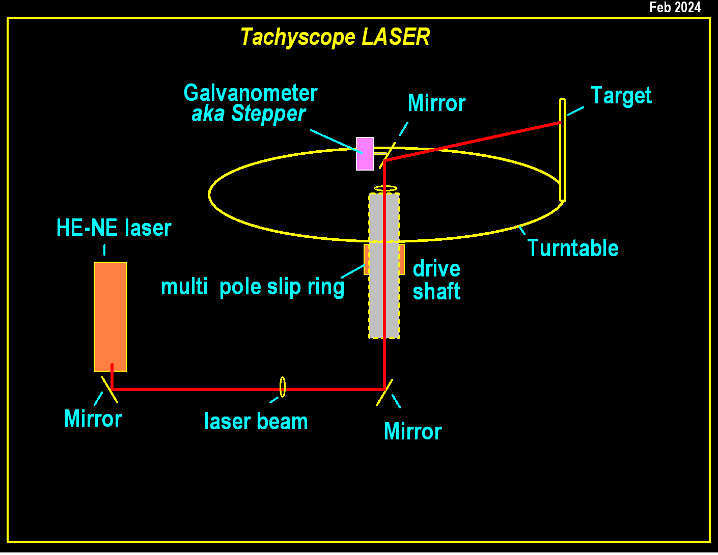
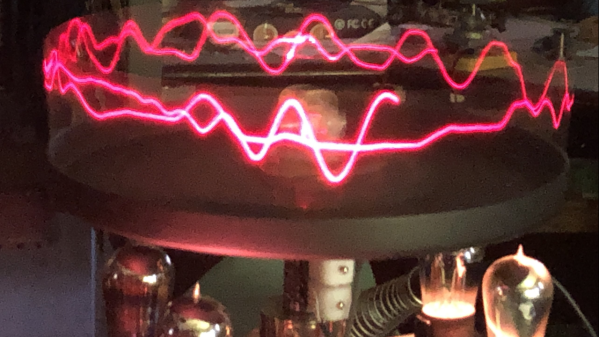
The laser is a good old-fashioned helium–neon tube — something we see less and less of in this era of solid state lasers — and the wavelength gives the waveform display a retro charm. The actual display is unique in our experience, with the beam shining up through a hollow shaft to bounce off a galvanometer mirror on a spinning platform. Galvo sweeps the laser across a translucent target, which creates the waveform by persistence of vision as it spins at 100 RPM or so.
Does the fact that the audio signal feeds through a tube amp to drive the single galvanometer actually improve the visuals? Only in the sense that those tubes make the steampunk-style enclosure look really, really cool, as does the exposed laser tube. That all of the steampunk elements obviously have a point to them rather than just being a another “glue some gears on it” project is icing on the laser-flavored cake.
The contest runs until July 23rd, so there’s lots of time to get laserin’ — and remember that there are categories for DIY lasers and anything that isn’t a display, just in case you think this project puts the bar too high for a light show. We’ve actually featured one of [Daniel]’s tachyscope waveform visualizers before, but that one, madly enough, spun an actual CRT.

Continue reading “2026 Frikkin Lasers Contest: Steampunk, 360 O-Scope Does It With Tubes”