For our 2025 Component Abuse Challenge there have been a set of entries which merely use a component for a purpose it wasn’t quite intended, and another which push misuse of a part into definite abuse territory, which damages or fundamentally changes it. [Ken Yap]’s use of a transistor base-emitter junction as a voltage reference certainly fits into the latter category.
If you forward bias a base-emitter junction, it will behave as a diode, which could be used as a roughly 0.7 volt reference. But this project is far more fun than that, because it runs the junctions in reverse biased breakdown mode. Using one of those cheap grab bags of transistor seconds, he finds that devices of the same type maintain the same voltage, which for the NPN devices he has works out at 9.5 volts and the PNP at 6.5. We’re told it damages their operation as transistors, but with a grab bag, that’s not quite the issue.
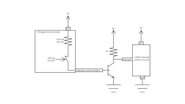
Part of setting up a microcontroller when writing a piece of firmware usually involves configuring its connections to the outside world. You define a mapping of physical pins to intenral peripherals to decide which is an input, output, analogue, or whatever other are available. In some cases though that choice isn’t available, and when you’ve used all the available output pins you’re done. But wait – can you use an input as an output? With [SCART VADER]’s lateral thinking, you can.
The whole thing takes advantage of the internal pull-up resistor that a microcontroller has among its internal kit of parts. Driving a transistor from an output pin usually requires a base resistor, so would it be possible to use the pullup as a base resistor? If the microcontroller can enable or disable the resistor on an input pin then yes it can, a transistor can be turned off and on with nary an output to be seen. In this case the chip is from ATmega parts bin so we’re not sure if the trick is possible on other manufacturers’ devices.
As part of our 2025 Component Abuse Challenge, this one embodies the finest principles of using a part in a way it was never intended to be used, and we love it. You’ve still got a few days to make an entry yourself at the time of writing this, so bring out your own hacks!
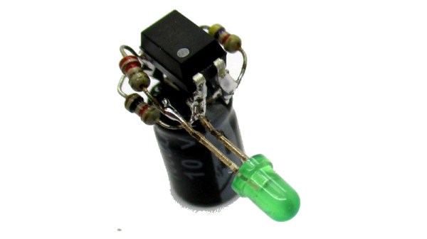
There’s a part you’ll find in almost every mains powered switch mode power supply that might at first appear to have only one application. An optocoupler sits between the low voltage and the high voltage sides, providing a safely isolated feedback. Can it be used for anything else? [b.kainka] thinks so, and has proved it by making an optocoupler powered LED flasher.
If a part can be made to act as an amplifier with a gain greater than one, then it should also be possible to make it oscillate. We’re reminded of the old joke about it being very easy to make an oscillator except when you want to make one, but in this case when an optocoupler is wired up as an inverting amplifier with appropriate feedback, it will oscillate. In this case the rather large capacitor leading to a longish period, enough to flash an LED.
We like this circuit, combining as it does an unexpected use for a part, and a circuit in which the unusual choice might just be practical. It’s part of our 2025 Component Abuse Challenge, for which you just about still have time to make an entry yourself if you have one.
The flip-flop, in whichever of its several forms you encounter it, is a staple of logic design. Any time that you need to hold onto something, count, or shift bits, out it comes. We expect a flip-flop to be an integrated circuit if we use one, but most of us could knock one together with a couple of transistors.
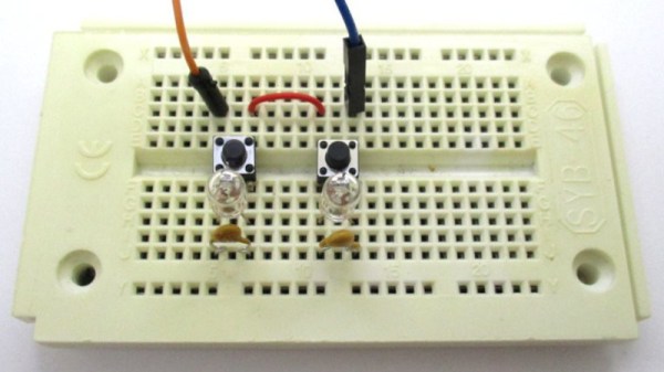
The circuit is simplicity itself, a pair of incandescent bulbs in series, each in turn in parallel with a momentary action switch and a PTC fuse. On start-up both fuses are conducting, so one or other of them will do its job as a fuse and go high impedance. At that point its bulb will light and the other fuse will remain low impedance so its bulb will stay dark. Press the switch across the lit bulb for a few seconds however, and the circuit resets itself. The other fuse goes high impedance while the first fuse returns to low impedance, and the other bulb lights.
We’re not sure we can see much in the way of practical application for this circuit, but sometimes merely because you can is reason enough. It’s part of our 2025 Component Abuse Challenge, for which you just about still have time to make an entry yourself if you have one.
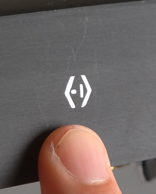
One of the hardest parts of a project — assuming it makes it that far — is finishing it up in an aesthetically pleasing manner. As they say, the devil is in the details, wearing Prada. Apparently the devil also has an excellent manicure, because [Tamas Feher] has come up with a way to introduce incredibly detailed decals (down to 0.1 mm) in cheap, repeatable fashion, using a technique borrowed from the local nail salon.
The end result can look quite a bit better than the test piece above.
For those who aren’t in to nail art (which, statistically speaking, is likely to be most of you) there is a common “stamping” technique for putting details onto human fingernails. Nail polish is first applied to voids on a stencil-like plate, then picked up by a smooth silicone stamper, which is then pressed against the nail, reproducing the image that was on the stencil. If that’s clear as mud, there’s a quick demo video embedded bellow.
There’s a common industrial technique that works the same way, which is actually where [Tamas] got the idea. For nail salons and at-home use, there are a huge variety of these stencils commercially available for nail art, but that doesn’t mean you’re likely to find what you want for your project’s front panel.
[Tamas] points out that by using a resin printer to produce the stencil plate, any arbitrary text or symbol can be used. Your logo, labels, whatever. By printing flat to the build plate, you can take advantage of the full resolution of the resin printer — even an older 2 K model would more than suffice here, while higher res like the new 16 K models become the definition of overkill. The prints go quick, as they don’t need any structural thickness: just enough to hold together coming off of the plate, plus enough extra to hold your designs at a 0.15 mm inset. That doesn’t seem very thick, but remember that this only has to hold enough nail polish to be picked up by the stamper.
[Tamas] cautions you have to work fast, as the thin layer of nail polish picked up by the stamper can dry in seconds. You’ll want plenty of nail polish remover (or plain acetone) on hand to clean the stamper once you’ve finished, as well as your stencil. [Tamas] cautions you’ll want to clean it immediately if you ever want to use it again. Good to know.
While this is going outside of the nail art kit’s comfort zone, it might not quite be abuse. It is however a very useful technique to add to our ever-growing quiver of how to make front panels. Besides, we don’t specify you have to literally make components suffer; we just want to see what wild and wonderful substitutions and improvisations you all come up with.
Conductive filament is a meltable resistor, which, if one squints hard enough, is basically a fuse.
In theory a 3D printed fuse works the same as a normal one: excessive current draw will cause the conductive plastic to briefly become a heater, causing it to self-destruct and break the electrical connection. There’s a risk of melted plastic and perhaps a nonzero combustion risk, but [JohnsonFarms.us] is less interested in whether this is a good idea and more interested in whether it can work at all, and with what degree of predictability and/or regret.
His experiments so far show that printed fuses are essentially meltable resistors with values between 300 Ω and 1250 Ω, depending on shape. What it takes to bring those to roughly 60 °C, where PLA softens, and around 150 °C, where PLA melts, is next on the to-do list.
Whatever conclusions are reached, it is interesting to think of conductive filament as a meltable resistor, and ponder what unusual applications that might allow.
Most conductive filaments have high resistance, but not all. Some, like Electrifi by Multi3D, have extremely low resistance and were used in a project that made 3d-printed logic gates.
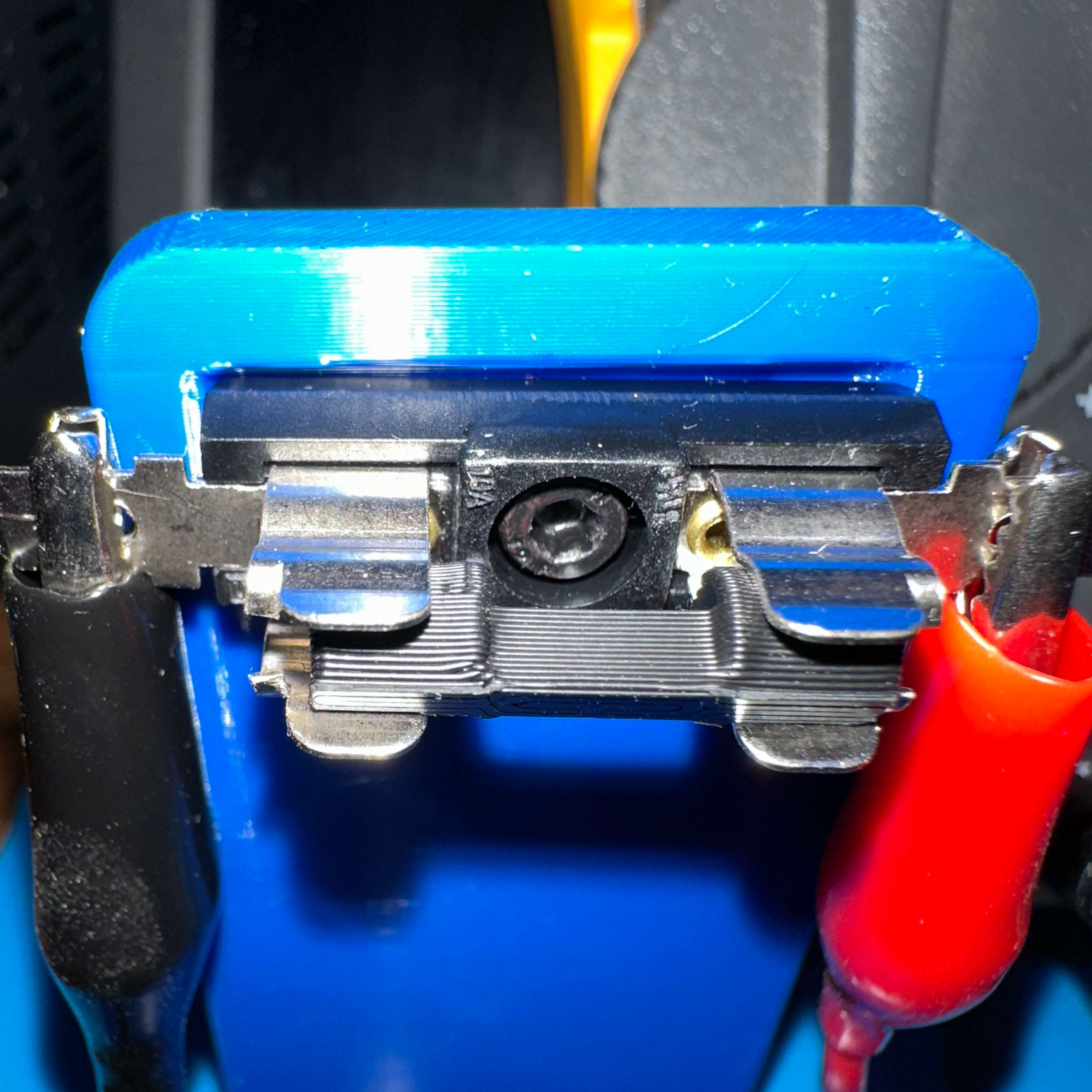
[Tito] entered a Self-Charging LED Flasher into the Component Abuse Challenge. It’s a simple re-build of a design by the unstoppable [Burkhard Kainka], and while [Tito] doesn’t explain its workings in detail, it’s a clever experiment in minimalism, and a bit of a head-scratcher at the same time.
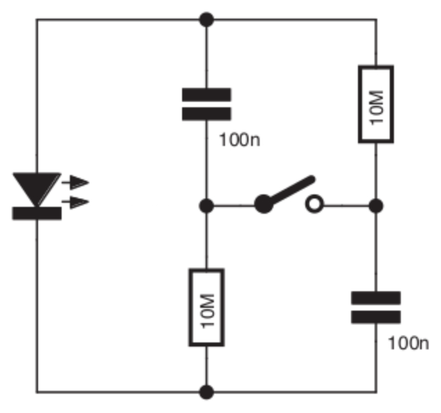
You press a button and an LED flashes. But there is no battery, so how does it work? Maybe the schematic to the right here will help. Or does it confound? Look at it yourself before reading on and see if you can figure out how it works.