Measuring Frequency Response With An RTL-SDR Dongle And A Diode

[Hans] wanted to see the frequency response of a bandpass filter but didn’t have a lot of test equipment. Using an RTL-SDR dongle, some software and a quickly made noise generator, he still managed to get a rough idea of the filter’s characteristics.

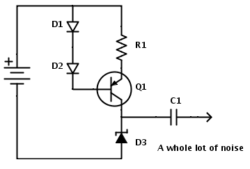
How did he do it? He ‘simply’ measured his noise generator frequency characteristics with and without the bandpass filter connected to its output and then subtracted one curve with the other. As you can see in the diagram above, the noise generator is based around a zener diode operating at the reverse breakdown voltage. DC blocking is then done with a simple capacitor.

Given that a standard RTL-SDR dongle can only sample a 2-3MHz wide spectrum gap at a time, [Hans] used rtlsdr-scanner to sweep his region of interest. In his write-up, he also did a great job at describing the limitations of such an approach: for example, the dynamic range of the ADC is only 48dB.

Building A Mesh Networked Conference Badge

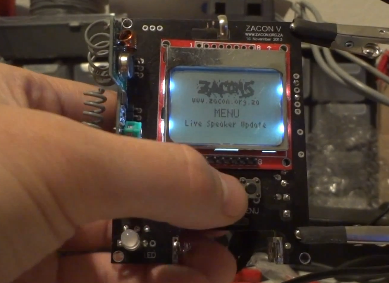
[Andrew] just finished his write-up describing electronic conference badges that he built for a free South African security conference (part1, part2). The end platform shown above is based on an ATMega328, a Nokia 5110 LCD, a 433MHz AM/OOK TX/RX module, a few LEDs and buttons.

The badges form a mesh network to send messages. This allows conversations between different attendees to be tracked. Final cost was the main constraint during this adventure, which is why these particular components were chosen and bought from eBay & Alibaba.

The first PCB prototypes were CNC milled. Once the PCB milling was complete there was a whole lot of soldering to be done. Luckily enough [Andrew]’s friends joined in to solder the 77 final boards. He also did a great job at documenting the protocol he setup, which was verified using the open source tool Maltego. Click past the break to see two videos of the system in action.

Continue reading “Building A Mesh Networked Conference Badge” →

OLED display, blue LED and Smartcard

Developed On Hackaday: Olivier’s Design Rundown

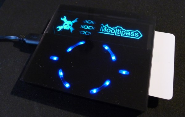
The Hackaday writers and readers are currently working hand-in-hand on an offline password keeper, the Mooltipass. A few days ago we presented Olivier’s design front PCB without even showing the rest of his creation (which was quite rude of us…). We also asked our readers for input on how we should design the front panel. In this new article we will therefore show you how the different pieces fit together in this very first (non-final) prototype… follow us after the break!

Continue reading “Developed On Hackaday: Olivier’s Design Rundown” →

OLED display, blue LED and Smartcard

Developed On Hackaday: The Top PCB Dilemna

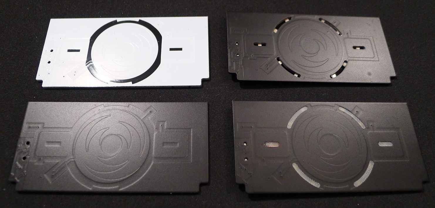
The Hackaday community offline password keeper is slowly coming together. A few days ago we received the top PCB for Olivier’s design (shown above). If you look at the picture below, you may see the problem we discovered when opening our package: the soldermask was the wrong color! Given the board is meant to be placed behind a tinted acrylic panel, this was quite a problem…

After using some spray paint, we managed to get to the point shown in the bottom left of the picture. The next task was to find the best way to illuminate the input interface with reverse mount LEDs. Using a CNC mill we machined openings (top right PCB) but also removed some epoxy on both PCB’s sides, thinking it would provide a better light diffusion. We then wrote part of the Mooltipass PWM code and took these pictures:

Continue reading “Developed On Hackaday: The Top PCB Dilemna” →

DIY Linear Actuators For A Flight Sim

[Roland] has already built a few very cool and extremely realistic flight sims, but his latest project will put his current rig to shame. He’s building a six degree of freedom simulator based on homebuilt linear actuators of his own design.

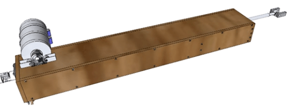
The actuator is powered by a large DC motor moving timing belts along the length of the enclosure. These timing belts are connected to a shaft that’s coupled to the frame with a few bungee cords. The bungee cords are important; without them, the timing belts would be carrying all the load of the sim – not a good thing if these actuators are moving an entire cockpit around a living room.

Also on [Roland]’s list of awesome stuff he’s building for his flight sims is a vibration system based on the BFF Shaker. This board takes data in from sim software and turns it into vibrations produced by either unbalanced DC motors or one of those ‘bass kicker’ transducers.

It’s all very cool stuff, and with all the crazy upgrades [Roland] is doing to his sim rig, he’s doing much better than paying $300/hour to rent a Beechcraft Baron.

Continue reading “DIY Linear Actuators For A Flight Sim” →

ISPnub – A Stand-Alone AVR In-System-Programmer Module

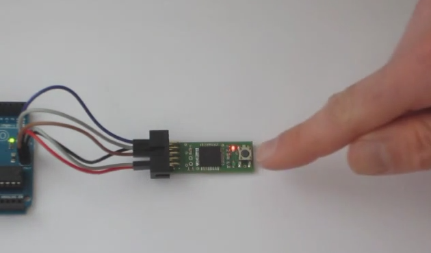
[Thomas] tipped us about his latest project: a stand-alone AVR programmer module named ISPnub. As you can see in the picture above, it is a simple circuit board composed of a main microcontroller (ATmega1284p), one button and two LEDs. Programming a target is a simple as connecting the ISPnub and pressing the button. The flashing operation success status is then shown using the green/red LED.

ISPnub gets its power from the target circuit so no external power supply is needed. It works over a wide voltage range: 1.8V to 5.5V. The module also features a programming counter which can be used to limit the number of programming cycles. A multi-platform Java tool is in charge of embedding the target flash contents with the ISPnub main firmware. The complete project is open source so you may want to check out the official GitHub repository for the firmware and the project’s page for the schematics.

Developed On Hackaday: 2 Days Left To Submit Your Design!

We’re sure that many of Hackaday readers already know that one of the two main components of the Mooltipass project is a smart card, containing (among others) the AES-256 encryption key. Two weeks ago we asked if you’d be interested coming up with a design that will be printed on the final card. As usual, many people were eager to contribute and recently sent us a few suggestions. If you missed the call and would like to join in, it’s not too late! You may still send your CMYK vector image at mathieu[at]hackaday[dot]com by sunday. More detailed specifications may be found here.

In a few days we’ll also publish on Hackaday a project update, as we recently received the top and bottom PCBs for Olivier’s design. The low level libraries will soon be finished and hopefully a few days later we’ll be able to ship a few devices to developers and beta testers. We’re also still looking for contributors that may be interested in helping us to develop browser plugins.

The Mooltipass team would also like to thank our dear readers that gave us a skull on Hackaday projects!