A High-Speed Logic Gate Board For The Easy-Phi Project

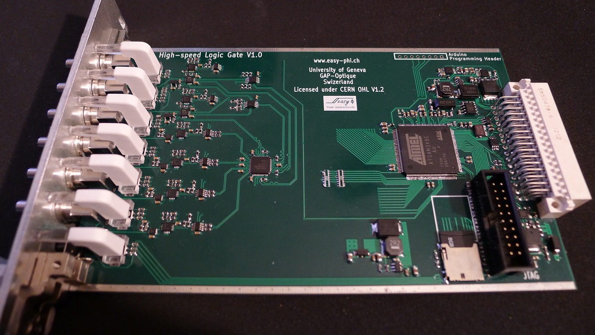
A (long) while ago I presented you the Easy-phi project, which aims at building a simple, cheap but intelligent rack-based open hardware/software platform for hobbyists. With this project, you simply have a rack to which you add cards (like the one shown above) that perform the functions you want.

During these last months my team has been finishing the design and production of several different boards so I’ll start showing them off during these next weeks. Today I present you the High Speed Logic Gate Board, a quantum-physicist requested easy-phi module that can perform logic AND/OR functions at <2GHz speeds. This quite technical write-up is mainly about the constraints that high-speed signals pose for schematics design but is also about the techniques that are used for HS signals termination and monitoring. I hope, however, it’ll give our readers a nice overview of what the insides of a high-speed system may look like. All the files used for this board may be found on the official GitHub repository.

I2S Audio And SPI Display With An Ethernet Module

LCD[kgsws] is working on a small project that requires some audio and a display of some sort. While this project can be easily completed with a bigish microcontroller or ARM board, he’s taking a much simpler route: the entire project is built around a cheap router module, giving this project amazing expandability for a very meager price.
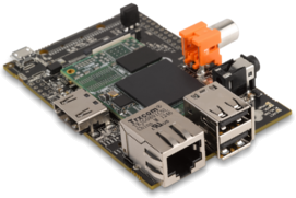
The router module in question is the HLK-RM04 from Hi-Link, commonly found via the usual Chinese resellers for about $25. On board this module is a UART, Ethernet, and a WiFi adapter along with a few GPIO pins for interfacing with the outside world.

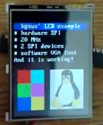
[kgsws] is using the native SPI pins on this module to control the clock and data lines for the tiny LCD, with a GPIO pin toggling the chip select. I2S audio is also implemented, decoded with an 8-bit DAC, the MCP4801.

It’s an extremely inexpensive solution for putting audio and video in a project, and since this board has Ethernet, WiFi, and a few more GPIO pins, it’s can do much more than whatever [kgsws] is planning next.

HummingBoard, The Vastly More Powerful Raspi

The Raspberry Pi has been around for a while now, and while many boards that hope to take the Pi’s place at the top of the single board ARM Linux food chain, not one has yet succeeded. Finally, there may be a true contender to the throne. It’s called the HummingBoard, and packs a surprising amount of power and connectivity into the same size and shape as the venerable Raspberry Pi.

The HummingBoard uses a Freescale i.MX6 quad core processor running at 1GHz with a Vivante GC2000 GPU. There’s 2GB of RAM, microSD card slot, mSATA connector, Gigabit Ethernet, a BCM4329 WiFi and Bluetooth module, a real-time clock, and IR receiver. There’s also all the usual Raspberry Pi flair, with a 26 pin GPIO connector, CSI camera connector, DSI LCD connector,  stereo out, as well as the usual HDMI and analog video.

The company behind the HummingBoard, SolidRun, hasn’t put a retail price on the board, nor have they set a launch date. You can, however, enter a contest to win a HummingBoard with the deadline this Friday. Winners will be announced in early May, so maybe the HummingBoard will be officially launched sometime around then.

It’s an amazing board with more than enough power to rival the extremely powerful BeagleBone Black, with the added bonus of being compatible with so many of those Raspberry Pi accessories we all love dearly.

Developed On Hackaday: Vote For Your Favorite Card Art

A few weeks ago we asked our dear readers if they were interested in coming up with some card art for the Mooltipass project. We received more than a dozen of them and a few days ago the HaD project Mooltipass followers/Mooltipas Google group recipients voted for their favorite ones.

Today we’ll present you the three popular ones and ask you to pick your favorite, so please follow us after the break…

Continue reading “Developed On Hackaday: Vote For Your Favorite Card Art”

A LIN Bus Signal Injector

LIN bus signal injector

[Zapta] tipped us about his latest project: a LIN bus signal injector. For our unfamiliar readers, the LIN bus is a popular automotive bus that is used to interface with buttons, lights, etc. As [Zapta] was tired of having to press the Sport Mode button of his car each time he turned the ignition on, he thought it’d build the platform shown above to automatically simulate the button press.

The project is based around an ATMega328 and is therefore Arduino IDE compatible (recognized as an Arduino Mini Pro), making firmware customization easy. In the car, it is physically setup as a proxy between the LIN master and the slave (which explains the two 3-wires groups shown in the picture). It is interesting to note that the injection feature can be toggled by using a particular car buttons press sequence. The project is fully open source and a video of the system in action is embedded after the break.

Continue reading “A LIN Bus Signal Injector”

Measuring Frequency Response With An RTL-SDR Dongle And A Diode

[Hans] wanted to see the frequency response of a bandpass filter but didn’t have a lot of test equipment. Using an RTL-SDR dongle, some software and a quickly made noise generator, he still managed to get a rough idea of the filter’s characteristics.

How did he do it? He ‘simply’ measured his noise generator frequency characteristics with and without the bandpass filter connected to its output and then subtracted one curve with the other. As you can see in the diagram above, the noise generator is based around a zener diode operating at the reverse breakdown voltage. DC blocking is then done with a simple capacitor.

Given that a standard RTL-SDR dongle can only sample a 2-3MHz wide spectrum gap at a time, [Hans] used rtlsdr-scanner to sweep his region of interest. In his write-up, he also did a great job at describing the limitations of such an approach: for example, the dynamic range of the ADC is only 48dB.

Building A Mesh Networked Conference Badge

[Andrew] just finished his write-up describing electronic conference badges that he built for a free South African security conference (part1, part2). The end platform shown above is based on an ATMega328, a Nokia 5110 LCD, a 433MHz AM/OOK TX/RX module, a few LEDs and buttons.

The badges form a mesh network to send messages. This allows conversations between different attendees to be tracked. Final cost was the main constraint during this adventure, which is why these particular components were chosen and bought from eBay & Alibaba.

The first PCB prototypes were CNC milled. Once the PCB milling was complete there was a whole lot of soldering to be done. Luckily enough [Andrew]’s friends joined in to solder the 77 final boards. He also did a great job at documenting the protocol he setup, which was verified using the open source tool Maltego. Click past the break to see two videos of the system in action.

Continue reading “Building A Mesh Networked Conference Badge”