Developed On Hackaday: First Feedback From Users

2013-12_Developed_on_Hackaday

Holy cr*p guys… we were amazed by the quantity of positive feedback that was left in the comments section of our last article. We have been featured by Slashdot ! We got plenty of project name suggestions, therefore we organized a poll located at the end of this post to let you decide which one is best. I also received many emails from people eager to start contributing to this offline password keeper project. If you missed the call and want to get involved, it’s still not too late. You can get in touch with me @ mathieu[at]hackaday[dot]com. So far, we have many beta testers, several software developers, one security assessor and a few firmware developers. Next step is to create a mailing list and a Hackaday forum category once the project’s name has been chosen.

Obviously, the very first post of our “Developed On Hackaday” series was to gauge your initial reactions to this ‘new’ project. Notice here the double quotes, as when someone has a new idea there usually are only two possibilities that may explain why it doesn’t exist in the market yet: either it is completely stupid or people are already working on it. In our case, it seems we are in the second category as many readers mentioned they wanted to work/were working/had worked on a similar product. As we’re selfish, we offered them to contribute to this new device.

To ensure that all of our readers are on the same page as to how the device will work we embedded a simple block diagram after the break, as well as a list of all new functionalities that we want to implement given the feedback we received. So keep reading to see what the future holds, as well as to vote on this new project’s name…

Continue reading “Developed On Hackaday: First Feedback From Users”

Developed On Hackaday: Let’s Build Some Hardware!

We’re pretty sure that most of you already know that a few months ago Hackaday was bought by SupplyFrame, who therefore became our new evil overlords. We do hope you’ve noticed that they’re actually quite nice, and in their divine goodness they recently gave the go-ahead on this series called Developed on Hackaday.

A new project will be made by the Hackaday staff & community and will hopefully be brought to the consumer market. For those who don’t have the time/experience to get involved in this adventure, we want to show and document what it takes to bring an idea to the marketable product stage. For the others, we would like to involve you in the design/development process as much as possible. Obviously, this project will be open source hardware/software. This time around, the hardware will mainly be developed by yours truly. You may already know me from the whistled platform (currently sold on Tindie) or from all the different projects described on my website, which makes this new adventure far from being my first rodeo.

What’s in it for the contributors? During all the steps of this project, we’ll offer many rewards as well as hand-soldered first prototypes of the device so you can start playing/testing it. Nothing is set in stone so every suggestion is welcome. Should we make a Kickstarter-like campaign to manufacture the final product, we’ll only do so once our prototype is final, our partners are chosen and all details of the production process are set and confirmed. In that case, we will just need to gather the required funds to make the device a reality. What are we going to build? Keep reading to find out.

Continue reading “Developed On Hackaday: Let’s Build Some Hardware!”

Using Ultrasonic Sensors To Measure And Log Oil Tank Levels

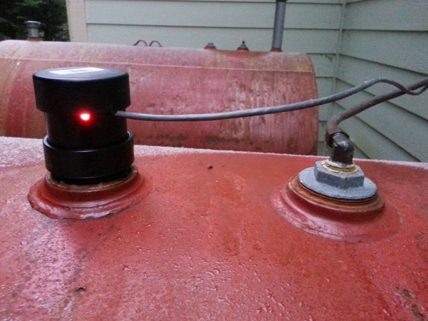
[Mike] lives in a temperate rainforest in Alaska (we figured from his website’s name) and uses a 570 gallon oil tank to supply his furnace. Until now, he had no way of knowing how much oil was left in the tank and what his daily usage was. As he didn’t find any commercial product that could do what he wanted, he designed his own solution. In his write-up, [Mike] started by listing all the different sensors he had considered to measure the oil level and finally opted for an ultrasonic sensor. In his opinion, this kind of sensor is the best compromise between cost, ease of use, range and precision for his application. The precise chosen model was the ping))) bought from our favorite auction website for around $2.5.

[Mike] built the custom enclosure that you can see in the picture above using PVC parts. Enclosed are the ultrasonic sensor, a temperature sensor and an LED indicating the power status. On the other side of the CAT5 cable can be found an Arduino compatible board with an XBee shield and a 9V battery. Using another XBee shield and its USB adapter board, [Mike] can now wirelessly access the tank oil level log from his computer.

Easy Capacitive Touch Sensors In Eagle

board

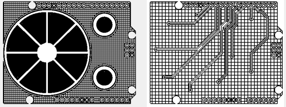
Capacitive sensing libraries for the Arduino and just about every other microcontroller platform have been around for ages now, but if you’d like to put a slightly complex cap sense pad in a PCB without a lot of work, you’re kind of out of luck. Not only do you need a proper education in how capacitors work, but a custom cap sense pad also requires some advanced knowledge of your preferred PCB layout program.

The folks over at PatternAgents have just the solution for this problem. They created an Eagle library of touch widgets that includes everything from buttons, linear and radial sliders, touchpads, and a whole lot more.

The simplest cap sense pad is just a filled polygon on the top layer of a board, but this simple setup isn’t ideal if you want to use Eagle’s autorouter. By playing with the restrict layers in Eagle, PatternAgents were able to create easy cap sense buttons that will work perfectly, without the problems of the autorouter placing traces willy-nilly.

There are more than enough parts to replicate a whole lot of touch interfaces – buttons can easily be made into a smallish keyboard, and the radial touch sensor will emulate the ‘wheel’ interface on an iPod. Very cool stuff, and we can’t wait to see these in a few more boards.

DIY Thermal Imaging Camera

Thermal imaging cameras – those really useful devices that give you Predator vision – are incredible tools. If you’re looking for heat escaping your house through a window, or just trying to figure out where your electronics project will explode next, they’re invaluable, if expensive, tools. [Kaptein QK] figured out an easy and cheap way to make your own thermal imaging camera using nothing just a few dollars worth of parts.

[Kaptein] based his camera off of a non-contact IR temperature gun. This device is useful for spot checking temperatures, but can’t produce an IR image like it’s $1000 cousins. By taking the thermopile out of this temperature gun, adding an op-amp, an A/D converter, and connecting it to an Arduino Nano with pan and tilt servos, [Kaptein] was able to slowly scan the thermopile over a scene and generate an image.

In the video below, you can see [Kaptein]’s scanning camera in action reading the ambient temperature and creating an imaging program for his PC. It works very well, and there a lot more [Kaptein] can improve on this system; getting rid of the servos and moving to mirrors would hopefully speed everything up, and replacing the 8-bit grayscale display with colors would give a vastly improved dynamic range.

Continue reading “DIY Thermal Imaging Camera”

Making A UNIX Clock While Making A Few Mistakes Along The Way

unixclock

Sometimes the projects we think are easy to design are the ones on which we end up making the most mistakes. The UNIX clock that you see in the picture above is one of these projects. For our readers that don’t know it, UNIX time is the number of seconds since 00:00 on January 1st 1970. The clock that [James] designed is based on an Arduino Pro Mini board, an RTC chip to store the time, a custom made display board and two buttons to set the date/time.

One of the mistakes that [James] made was designing the boards on which will be soldered the seven-segment displays before actually choosing the ones he’ll use, as he was thinking they’d be all the same. The displays he ended up with had a different pitch and needed a different anode voltage, so he had to cut several traces on the PCBs and add another power supply. It also took [James] quite a while to remove the bits that his hackerspace’s laser didn’t cut through. We strongly advise a good look at his very detailed write-up if you are starting in the electronics world.

If you find this Unix time display too easy to read here’s one that’s a bit more of a challenge.

Persistence Of Vision Planetary Map

POV planetary map

Looking at the looping GIF above you’re probably thinking, oh, another hard drive POV setup… Well… Not quite.

This is one of [Dev’s] latest projects, and it is a planetary map that shows the angular positions of all 8 of the major celestial bodies from any given date between 1800 and 2050. It’s also capable of showing analogue clock hands, the phases of the moon, and other simple graphics.

The main unit is a hard disk, but [Dev] milled off many of the features on it to give it a more exposed, purpose-built look. He designed the LED bearing PCB from scratch using EagleCAD, which sits on the back of the drive, with the spindle poking through. It has 8 rings of 5 surface mounted LEDs, which shine through opaque plastic diffuser rings that he printed using Shapeways — they feature small recesses to fit snugly on the board over the LEDs. On the top level is a 1mm thick black disc of some unknown material that [Dev] had sitting around, which now has 8 holes machined into it in the exact position of the LEDs.

A Cortex-M0 drives the LEDs using an LPCXpresso board which allows the LEDs to sit across only one byte of a hardware I/O port. On the software end, each rotation of the disk is segmented into three hundred and sixty 1 degree slices. This system allows him to achieve a circular resolution of 8×360 pixels at 25 frames per second. Not bad for a persistence of vision device!

Stick around after the break to see the rather entertaining demo video of the device.

Continue reading “Persistence Of Vision Planetary Map”