Interfacing With The HTC Desire Display And Its Touch Panel

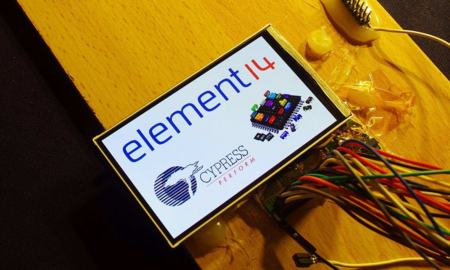
Part of [Linas]’ submission to last year’s Cypress Smarter Life Challenge involved using the HTC Desire display and its touch screen. This particular phone includes a full-color active-matrix OLED (AMOLED) display that has a 3.7″ diagonal and a 480×800 resolution, resulting in a 252ppi pixel density. Using a MSO2024B oscilloscope, [Linas] originally started his adventure with the touchscreen by sniffing the I2C signals. As some math was required to extract the data, he later found the HTC Desire source code and included it on his STM32F429 (so much for reverse engineering!).

After spending many hours searching for the AMOLED display and controller datasheets, [Linas] resorted to pay a company to get the resources he needed. He produced a custom-made PCB to provide the display with the required voltages, as well as offering a 0.1″ connector to interface with it. A RGB565 interface is used to communicate with the screen so only 65k out of the 16 million colors are used. You may download all the program files and datasheets in [Linas] write-up.

A Low Cost Dual Discriminator Module For The Easy-phi Project

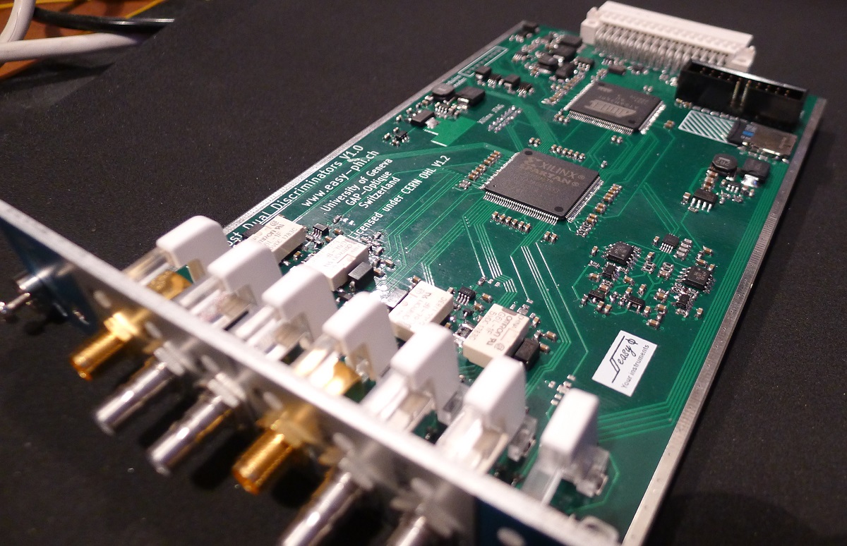
A few months ago I presented you the Easy-phi project, which aims at building a simple, cheap but intelligent rack-based open hardware/software platform for hobbyists. With easy-phi, you simply have a rack to which you add cards (like the one shown above) that perform the functions you want.

Recently my team finished testing our FPGA-based discriminator or “universal input” if you prefer. As easy-phi cards use a well-defined electrical signal to communicate with each other, we needed to make a card that would translate the different kinds of electrical signals from the outside, as well as perform plenty of other functions. It was therefore designed to have a 100MHz input bandwidth with an AC/DC coupled 50 ohm/high impedance input stage (x2) and 4 easy-phi outputs. For this module, we picked the (old) spartan3-an FPGA to perform the different logic functions that may be needed by the final users (high speed counter, OR/XOR/AND, pulse creation,…). Using the cortex-m3 microcontroller present on the board, it may be easily reconfigured at will. All design resources may be found on our Github, and you can always have a look at our official website.

Easy Multi-Touch Table

Screen Shot 2013-12-31 at 1.53.13 PM

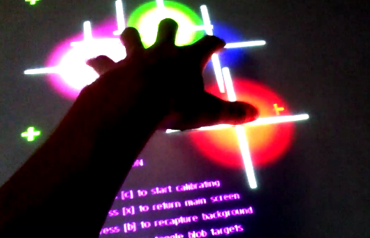
[2bigbros] put up an Instructable on his multi-touch table build. It’s a nice setup, using the typical frustrated total internal reflection method for touch sensing. Tinkerman’s Method was used for the screen itself, which involves rolling silicon onto vellum with a paint roller to improve the bond. [2bigbros] then built a nice aluminum and wooden frame for the whole thing. He’s light on some details, but most people with a basic understanding and Google will be able to figure it out.

This is a very accessible project for most builders. If you’re interested in getting into it, there are plenty of projects to reference. We previously covered the basics, as well as a more involved build. We’ve even seen an interactive tower defense game using multi-touch. If you decide to build one of your own, don’t forget the excellent resource at TUIO for finding frameworks and example implementations.

Continue reading “Easy Multi-Touch Table” →

USBPass – A Mooltipass-like Project

In our Developed on Hackaday series some readers may recall a sentence we wrote: “if one’s idea is not yet in the market, it’s either completely stupid or people are already working on it”. Well, [Josh] casually mentioned that he was also working on an offline password keeper after having recently subscribed to our google group. Similarly to the Hackaday-developed platform, the USBPass is connected to a computer via USB and is detected as an HID keyboard. As you can see in the picture shown above, it uses very few components: an ATMega32U2, a USB connector, three buttons and a few passives chips.

A total of 20 passwords can be stored in the microcontroller’s memory, which can be ‘typed’ by the platform using the push buttons. The USBPass firmware is based around the LUFA USB stack, to which [Josh] added HID report functionality to allow data transfer from his desktop application. The latter uses the Linux/Windows/OS X HID API library so bringing his software to other operating systems can be done in no time. All the project resources can be found on GitHub, while [Josh] is currently working on a B revision which will include an OLED screen.

Hacking SD Card & Flash Memory Controllers

We hope that some of our readers are currently at this year’s Chaos Communication Congress (schedule can be found here and live streams here), as many interesting talks are happening. One of them addressed hacking the memory controllers embedded in all memory cards that you may have. As memory storage density increases, it’s more likely that some sectors inside the embedded flash are defective. Therefore, all manufacturers add a small microcontroller to their cards (along with extra memory) to invisibly ‘replace’ the defective sectors to the operating system.

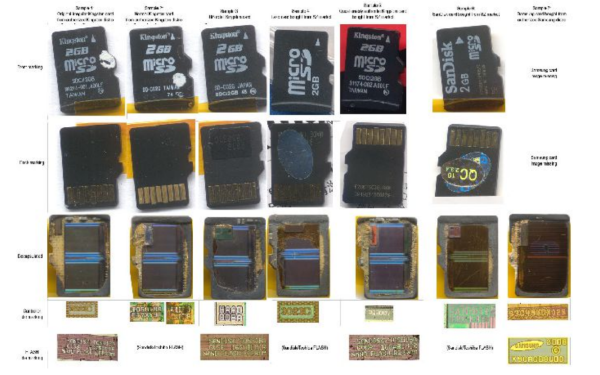
[Bunnie] and [xobs] went around buying many different microSD cards in order to find a hackable one. In their talk at 30C3 (slides here), they reported their findings on a particular microcontroller brand, Appotech, and its AX211/AX215. By reverse engineering the firmware code they found online, they discovered a simple “knock” sequence transmitted over manufacturer-reserved commands that dropped the controller into a firmware loading mode. From there, they were able to reverse engineer most of the 8051 microcontroller function-specific registers, allowing them to develop novel applications for it. Some of the initial work was done using a FPGA/i.MX6-based platform that the team developed named Novena, which we hope may be available for purchase some day. It was, among others, used to simulate the FLASH memory chip that the team had previously removed. A video of the talk is embedded below.

Continue reading “Hacking SD Card & Flash Memory Controllers” →

Developed On Hackaday: First Version Of The Hardware

mooltipass-schematic-featured

The Hackaday writers and readers are currently working hand-in-hand on an offline password keeper, the mooltipass (click to see the project description). 

Next in our Developed on Hackaday series, we present the first version of our schematics. There’s already been a lot of discussions going on in our dedicated Google group, mainly about the project’s basic functionality. Because our firmware developers wanted to get to work, we decided to send the first version of our hardware into production a few days ago. Before going through the schematics, let’s review the required list of the mooltipass’s core components:

  • an easily-readable screen
  • a read-protected smart-card
  • large flash memory to store the encrypted passwords
  • an Arduino-compatible microcontroller with USB connectivity

We’ve been drowning in component suggestions from motivated hobbyists, so we figured we’d make the mooltipass v1 as simple as possible and then move from there. Given this device is developed on Hackaday, we also wanted future users to modify it, building completely new projects based around these main components. Keep reading for our schematics…

Continue reading “Developed On Hackaday: First Version Of The Hardware” →

Testing Six Hundred Fish

fish

That’s the best and most obtuse title you’ll ever see for a Hackaday post, but surprisingly it’s pretty accurate. [Bob] over at the Sector67 hackerspace took part in a 111-day accelerator program in Shenzhen last year to improve his manufacturing skills. He’s just about ready to release his first product, a Bluetooth device that connects to an ice fishing tip-up. The blog for the device recounts the challenges of taking a project from a circuit to a finished product, and illustrates the difference between building something with an Arduino and selling thousands of devices.

The circuit boards for BlueTipz come in panels of eight, but what’s the best way to populate and solder five thousand devices in a reasonably short amount of time? [Bob] hired a few students from the local college to help him out in assembling all these devices. The plastic enclosures were made at a local plastics manufacturer, but the molds were made in China. The manufacturer needed to modify the molds a bit, but after a few days, [Bob] had five thousand enclosures ready to stuff full of electronics.

With the devices assembled, it’s time for programming, and that means building a programmer. [Bob] put all the guts for the device into a plastic box and 3D-printed a mount for the bare BlueTipz board. Put a board on the mount, press a button, and the tech now has a functioning device in his hands.

Besides manufacturing, there’s also a whole lot of testing that went into the design of BlueTipz. Because this is a device for ice fishing—a cold and potentially windy operating environment—[Bob] built a test rig in a freezer. The test rig triggers the device’s sensor, waits two minutes (the amount of time it would take for an ice fisherman to check the tip-up) and resets. They claim the battery life is good for 600 fish, and with this testing rig they were able to verify their calculated battery life with real-world data: without actually catching six hundred fish, of course.

Not only does [Bob] have a good bit of product development under his belt, he was also kind enough to go over the stuff everyday electronic design just doesn’t cover. Developing a product is something you can only learn by doing, and we’re glad [Bob] chose to share his experiences with us.