Modifying DD-WRT’s Protected GUI

hacking_the_ddwrt_gui

[Craig] is always keeping busy by deconstructing and poking around in various firmware images. This time around he has taken on the task of modifying the DD-WRT package, a popular replacement firmware for SOHO routers.

While the firmware is released under the GPL, [Craig] cites that it’s pretty difficult to build from source. Instead, he says that the typical course of action is to extract files from the firmware image, alter them, then reconstruct the image. This works for most things, but the DD-WRT GUI files are protected in order to prevent modification.

Since the phrase “you are not allowed to do that” doesn’t exist in his vocabulary, [Craig] set out to see if he could make his way around the protections and change the GUI code. It took quite a bit of digging around using IDA Pro and readelf, but he was eventually able to extract, tweak, then reinsert individual pages back into the firmware image.

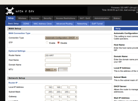
The process is pretty time consuming, so he put together a tool called webdecomp that automates the extraction and rebuilding of DD-WRT’s web page file. If you’re interested in rocking a custom Hackaday-branded router interface like the one shown above, be sure to swing by his site and grab a copy of webdecomp.

Video: Eagle CAD Layout

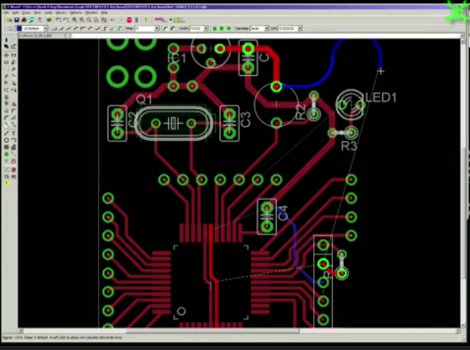
This week’s video is the last in a series of videos where we show how to use Eagle CAD. Today we will look a the Layout portion of the program and will create a circuit board from the schematic that we created previously. We start by creating a layout file and then moving all of the parts to appropriate places on the circuit board. After that, [Jack] shows how to route the traces. Along the way, he talks about the tools that he is using and various ways to use them. The end result is a prototyping board for the PIC18F44J11.

Like the others, this video is fairly long at 29 minutes, so make sure to have some time dedicated towards watching it if you do.

In next week’s video, we will be showing this board as it arrived to us from a manufacturer and will do a tutorial on how to solder.

If you have missed our previous videos, you can find them here:

Schematic part I
Schematic and Custom part creation
CAM Processor

We have also created many supplemental videos explaining how to use many of the tools in the tool palettes. You can find them on our Youtube channel:

Check out the video after the break!
Continue reading “Video: Eagle CAD Layout” →

Hackaday Birthday Cake!

[Alex], aka [Grovenstien] turned 30 this weekend. After a conversation with his sister, where she asked: “what was that website with the skull that you always look at?”, he thought maybe he’d get a sticker or a shirt. She surprised him with this totally awesome birthday cake! There really aren’t any build details, but you can pretty much see that it has LEDs for eyes as well as some crazy sparkler effects going on as well. What we’re particularly impressed with is the fact that everything was hand cut, even that crisp text at the bottom. Happy Birthday [Grovenstien] and awesome job big sister!

check out the rest of the pictures after the break.

Continue reading “Hackaday Birthday Cake!” →

Weekly Roundup 9/17/11

In case you missed them, here are our most popular posts from the past week.

Our most popular post from the past week was one where we show a project where [Linas] built his own CT scanner and then used those scans to create 3D models.

Our next most popular post was an Engine Hack from the previous theme where [Mike] built a jet out of pipe fittings and motorcycle parts.

Next up is a post that will be of interest to folks who like their privacy. This post shows a project that simulates a trip wire using a laser beam. The end result is the same though. Cross the beam, hear it scream.

Our forth most popular post was one about a robot that can climb walls and then parachute back down to do it again… provided that it has a team of students ready to catch it on a tarp at the bottom.

Finally, we have a post that describes how to create a circuit board out of a piece of glass. The author is using it for a touch-sensitive button interface.

Microchip Puts Up Two $1000 Prizes For USB And TCP/IP Stacks!

microchip_call_for_open_source

A couple of weeks ago we put up a post titled Addressing Microchip’s open source problem where we talked about some of their shortcomings as far as open source code goes, specifically the TCP/IP stack and the USB stack. The comments were predictably fairly negative. The interesting part here is that Microchip actually listened. If you read through all of the comments, you will get a bit of an inside look at what is going on internally at Microchip. At the very end, [Marc] from Microchip left a couple of comments outlining a pair of prizes for independently ported stacks for TCP/IP and USB. Microchip can’t fully open the ones that they have because of legal reasons so they need the help of the development community and they are putting up $1000 for each one to prove that they are serious. If you follow this link you will arrive at a page outlining the rules for the contest.

The gauntlet has been dropped! Do you have chops to pull this off and earn yourself a cool $1000?

Video – Eagle CAD’s CAM Processor

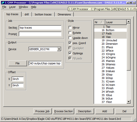
Here is the next installment in our series of Eagle CAD videos. In this video we skip ahead a bit and show off the CAM processor that you use to create the files necessary to have your circuit boards be manufactured. After watching this video, you will know how create a new CAM program, load a circuit board into the CAM processor, tell it where to save your files, and actually use it to create the files.

We’re skipping ahead today because of a screw up on our part. We meant to show the layout portion of the program today but edited the wrong video… We’ll show layout next week. After that, we will show the completed circuit board and solder the parts onto it.

If you are itching for some Eagle CAD layout info, you may be interested in some supplementary videos that we have uploaded to our Youtube channel. In those videos, we show how to use the most important features in the layout portion of the Eagle CAD.

Have you missed the previous videos? Here are some links to them:

Schematic and the beginning of a custom part: [click here]
More custom part stuff: [click here]

Video is after the break:
Continue reading “Video – Eagle CAD’s CAM Processor” →

Upverter: It’s Like Github For Hardware

If there’s one thing we’ve noticed about hardware hackery and electronics project, it’s that all the resources to build a project are scattered about the Internet on forums, blogs (heh), and personal web pages. Enter Upverter. The fellows who started Upverter had the same observation, and after some Y Combinator funding, launched what they hope to be “The Github of electronics” and the “Google Docs of hardware design.”

Upverter has the features we would expect – forking, versioning, and integration with Github for a project’s code. Already there’s a few cool projects, like a PIC programmer, a TV-B-Gone, and a tiny version of Conway’s Game Of Life.

We’re not ready to wave the banner of an Upverter fanboy quite yet. There’s quite a number of components available in the schematic editor, but from our experience the component library could use some refinement both by weeding out duplicates and increasing the number of parts. We’d also like to put a zoom control for the schematic view on our wish list. Upverter doesn’t have a PCB editor either, but from this post from a VC rag, the team is working on one. While this is really just nitpicking – Upverter launched less than 24 hours ago – we’ll be happy to see the some projects roll in on the tip line that are hosted on Upverter.

EDIT: link to the Google cache, because we probably Slashdotted it. It’s up for now.