Despite the best efforts of the manufacturers, there are folks out there that try to repair power tools, with [Dean Doherty] being one of them. Recently he got a Milwaukee M18 cordless planer in for repairs, which started off with just replacing some dodgy bearings, but ended up with diagnosing a faulty controller. Consequently the total repair costs went up from reasonable to absolutely unreasonable, leading to a rant on why Milwaukee tools are terrible to repair.
Among the symptoms was the deep-discharged battery, which had just a hair over 7 V while unloaded. Question was what had drained the battery so severely. What was clear was that the tool was completely seized after inserting a working battery with just a sad high-pitched whine from a stalled motor.
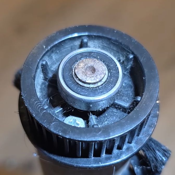
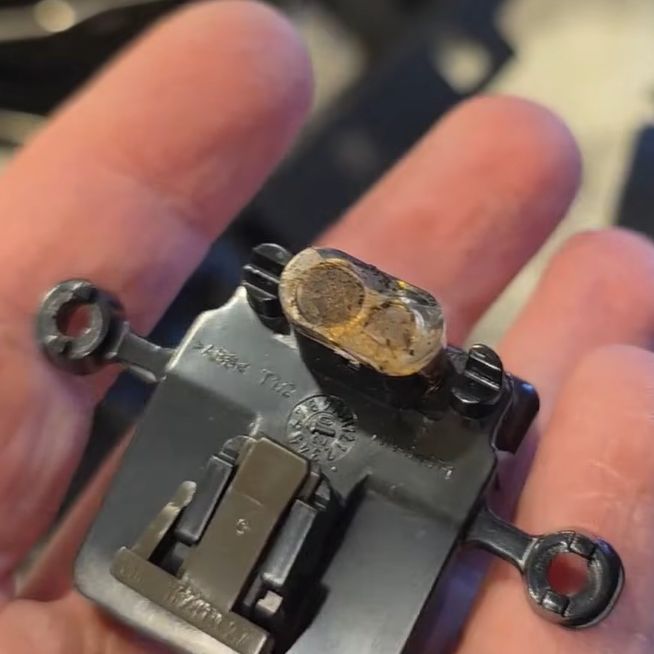
After replacing both bearings and grumbling about cheap bearings, the tool had a lot of drywall dust cleaned out and was reassembled for a test run. This sadly showed that the controller board had been destroyed due to the seized rotor bearing, explaining the drained battery. Replacing the controller would have cost €60-70 as it comes with the entire handle assembly, rendering the repair non-viable and a waste.
Perhaps the one lesson from this story is that you may as well preventively swap the cheap bearings in your Milwaukee tools, to prevent seizing and taking out the controller board. That said, we’d love to see an autopsy on this controller board fault.
Continue reading “The Dismal Repairability Of Milwaukee Tools”