In the process of making everything ‘smart’, it would seem that rings have become the next target, and they keep getting new features. The ring that [Aaron Christophel] got his mittens on is the SR08, which appears to have been cloned by many manufacturers at this point. It’s got an OLED display, 1 MB Flash and a Renesas DA14585 powering it from a positively adorable 16 mAh LiPo battery.
The small scale makes it an absolute chore to reverse-engineer and develop with, which is why [Aaron] got the €35 DA14585 development kit from Renesas. Since this dev kit only comes with a 256 kB SPI Flash chip, he had to replace it with a 1 MB one. The reference PDFs, pinouts and custom demo firmware are provided on his GitHub account, all of which is also explained in the video.
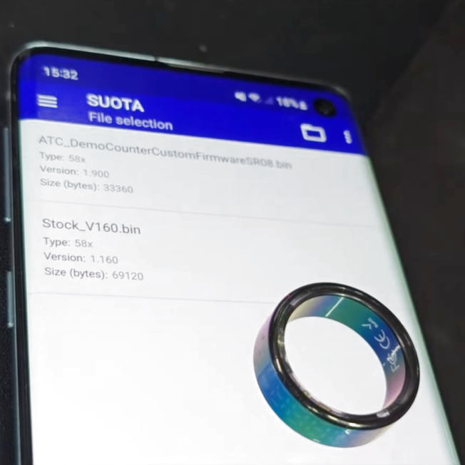
Rather than hack the ring and destroy it like his first attempts, [Aaron] switched to using the Renesas Software Update OTA app to flash custom firmware instead. A CRC error is shown, but this can be safely ignored. The ring uses about 18 µA idle and 3 mA while driving the display, which is covered in the provided custom firmware for anyone who wants to try doing something interesting with these rings.
Continue reading “Hacking The 22€ BLE SR08 Smart Ring With Built-In Display”