You don’t see them much anymore, but there was a time when any hobbyist who dealt with RF probably had a grid dip meter. The idea was to have an oscillator and measure the grid current as it coupled to external circuits. At resonance, the grid current would go down or dip, hence the name. In the hands of someone who knew how to use it, the meter could measure inductance, capacitance, tuned circuits, antennas, and more. [Thomas] takes a peek inside a homebrew unit from the 1950s in a recent video you can see below.
These meters often have a few things in common. They usually have a plug-in coil near the top and a big tuning capacitor. Of course, there’s also a meter. You have to pick the right coil for the frequency of interest, which both sets the oscillator frequency range and couples to the circuit under test.
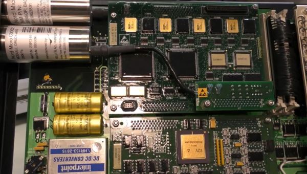
Modern passenger airliners are essentially tubes-with-wings, they just happen to be tubes that are stuffed full with fancy electronics. Some of the most important of these are related to keeping the bits of the tube with humans inside it at temperatures and pressures that keeps them alive and happy. Case in point the Boeing 777, of which [Michel] of Le Labo de Michel on YouTube recently obtained the Cabin Pressure Control System (CPCS) for a teardown.
The crucial parts on the system are the two Nord-Micro C0002 piezo resistive pressure transducers, which measure the pressure inside the aircraft. These sensors, one of which is marked as ‘backup’, are read out by multiple ADCs connected to a couple of FPGAs. The system further has an ARINC 429 transceiver, for communicating with the other avionics components. Naturally the multiple PCBs are conformally coated and with vibration-proof interconnects.
Although it may seem like a lot of hardware just to measure air pressure with, this kind of hardware is meant to work without errors over the span of years, meaning significant amounts of redundancy and error checking has to be built-in. Tragic accidents such as Helios Airways Flight 522 involving a 737-300 highlight the importance of these systems. Although in that case human error had disabled the cabin pressurization, it shows just how hard it can be to detect hypoxia before it is too late.
Would you feel confident in buying US-made LiFePO4 (LFP) batteries? While the answer here is generally expected to be ‘yes’, especially compared to getting an unbranded LFP battery off eBay from a random seller, the outcome may not be that different. Case in point the 100 Ah, 12 VDC LFP Battle Born battery that [Will Prowse] took a look at to see why its positive terminal gets positively crispy.
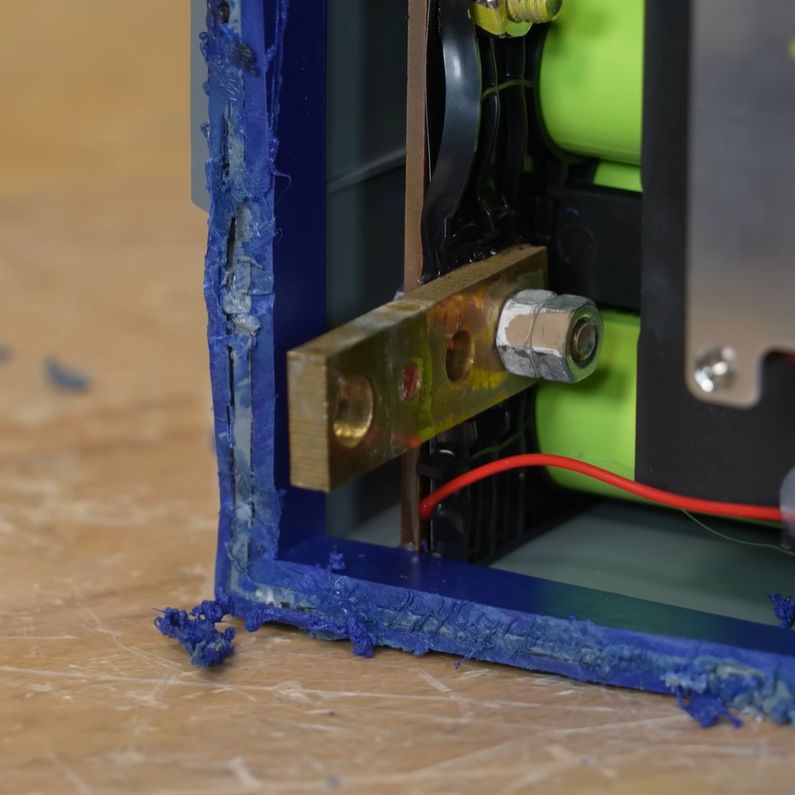
Battle Born battery positive terminal. (Credit: Will Prowse, YouTube)
Once the lid was cut off, it’s easy to see what the problem is: the positive terminal is only loosely attached to the bus bar, leading to extremely poor contact. It also appears that there’s a plastic spacer which has properly melted already in this well-used battery that [Will] obtained from a viewer.
This overheating issue with Battle Born batteries has been reported for years now, which makes it a great idea to take a good look at any Battle Born LFP batteries you may have kicking around, as they may be plagued by the same design flaw. Trying to make use of the manufacturer’s warranty could be complicated based on the commentators in the DIY Solar Forum thread, as Battle Born likes to claim that the overheating issue is an external problem and not a design flaw.
Either way, it looks like an incredibly sketchy way to design a battery terminal on an LFP battery that is supposed to surge 100+A. [Will] is requesting that anyone affected posts details in the forum or similar to get all information together, as he looks to push Battle Born on this issue.
What makes this issue worse is that shortly after releasing that first video, Battle Born responded to some concerned customers with a response that claims that their terminal design is a ‘thermal fail-safe’, but as can be seen in [Will]’s follow-up video, it absolutely doesn’t look like one.
Keychain cameras are rarely good. However, in the case of Walmart’s current offering, it might be worse than it’s supposed to be. [FoxTailWhipz] bought the Vivitar-branded device and set about investigating its claim that it could deliver high-resolution photos.
The Vivatar Retro Keychain Camera costs $12.88, and wears “FULL HD” and “14MP” branding on the packaging. It’s actually built by Sakar International, a company that manufactures products for other brands to license. Outside of the branding, though, [FoxTailWhipz] figured the resolution claims were likely misleading. Taking photos quickly showed this was the case, as whatever setting was used, the photos would always come out at 640 x 480, or roughly 0.3 megapixels. He thus decided a teardown would be the best way to determine what was going on inside. You can see it all in the video below.
Pulling the device apart was easy, revealing that the screen and battery are simply attached to the PCB with double-sided tape. With the board removed from the case, the sensor and lens module are visible, with the model number printed on the flex cable. The sensor datasheet tells you what you need to know. It’s a 2-megapixel sensor, capable of resolutions up to 1632 x 1212. The camera firmware itself seems to not even use the full resolution, since it only outputs images at 640 x 480.
It’s not that surprising that an ultra-cheap keychain camera doesn’t meet the outrageous specs on the box. At the same time, it’s sad to see major retailers selling products that can’t do what they say on the tin. We see this problem a lot, in everything from network cables to oscilloscopes.
If you have ever thought, “I wish I could have a mass spectrometer at home,” then we aren’t very surprised you are reading Hackaday. [Thomas Scherrer] somehow acquired a broken Brucker Microflex LT Mass Spectrometer, and while it was clearly not working, it promised to be a fun teardown, as you can see in the first part of the video below.
Inside are lasers and definitely some high voltages floating around. This appears to be an industrial unit, but it has a great design for service. Many of the panels are removable without tools.
The best part about BEV and hybrid cars is probably the bit where their electronics are taken out for a good teardown and comparison with previous generations and competing designs. Case in point: This [Denki Otaku] teardown of a fifth-generation Prius inverter and motor controller, which you can see in the video below. First released in 2022, this remains the current platform used in modern Prius hybrid cars.
Compared to the fourth-generation design from 2015, the fifth generation saw about half of its design changed or updated, including the stack-up and liquid cooling layout. Once [Otaku] popped open the big aluminium box containing the dual motor controller and inverters, we could see the controller card, which connects to the power cards that handle the heavy power conversion. These are directly coupled to a serious aluminium liquid-cooled heatsink.
At the bottom of the Prius sandwich is the 12VDC inverter board, which does pretty much what it says on the tin. With less severe cooling requirements, it couples its heat-producing parts into the aluminium enclosure from where the liquid cooling loop can pick up that bit of thermal waste. Overall, it looks like a very clean and modular design, which, as noted in the video, still leaves plenty of room inside the housing.
Regardless of what you think of the Prius on the road, you have to admit it’s fun to hack.
[Big Clive] picked up a tiny heater for less than £8 from the usual sources. Would you be shocked to learn that its heating capacity wasn’t as advertised? No, we weren’t either. But [Clive] treats us to his usual fun teardown and analysis in the video below.
A simple test shows that the heater drew about 800 W for a moment and drops as it heats until it stabilizes at about 300 W. Despite that, these units are often touted as 800 W heaters with claims of heating up an entire house in minutes. Inside are a fan, a ceramic heater, and two PCBs.
The ceramic heaters are dwarfed by metal fins used as a heat exchanger. The display uses a clever series of touch sensors to save money on switches. The other board is what actually does the work.
[Clive] was, overall, impressed with the PCB. A triac runs the heaters and the fan. It also includes a thermistor for reading the temperature.
You can learn more about the power supply and how the heater measures up in the video. Suffice it to say, that a cheap heater acts like a cheap heater, although as cheap heaters go, this one is built well enough.