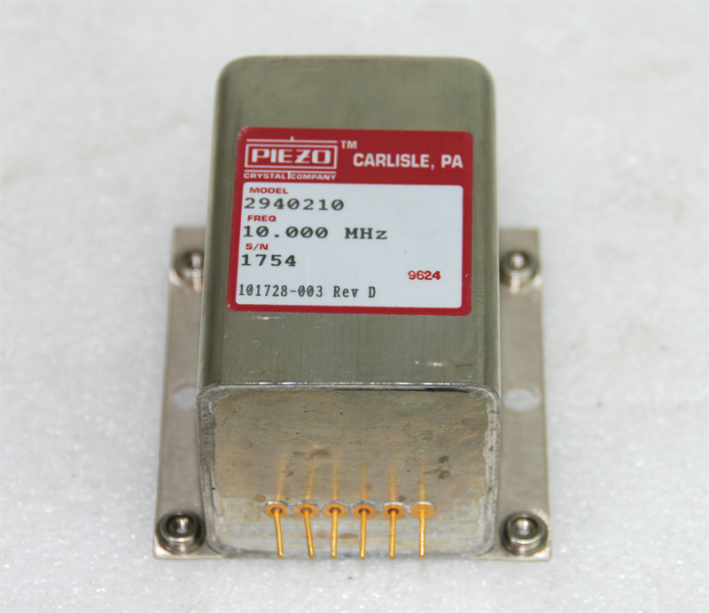
This GPS Disciplined Oscillator (GPSDO) project uses a Piezo 2940210 10 MHz crystal oscillator which is both oven-controlled (OCXO) and voltage-controlled (VCXO). The GPSDO takes the precision 1 Pulse-Per-Second (PPS) GPS signal and uses it to adjust the 10 MHz crystal oscillator until it repeatedly produces 10,000,000 cycles within one second.
[Wil] had trouble finding all the specs for the 2940210, particularly the EFC sensitivity (S), so after doing some research he did some experiments to fill in the blanks. You can get the gory details in his notes linked above.
Crystal oscillators are incredibly useful components, but they come with one little snag: their oscillation is temperature-dependent. For many applications the relatively small deviation is not a problem, but especially for precision instruments this is a deal breaker. Enter the oven controlled crystal oscillator, or OCXO. These do basically what it says on the tin, but what’s inside them? [Kerry Wong] took apart a vintage Toyocom TCO-627VC 10 MHz OCXO, revealing a lot more complexity than one might assume.
Inside the insulated enclosure there is of course the crystal oscillator itself, which has a heating coil wrapped around it. Of note is that other OCXOs that [Kerry] took apart had more insulation, as well as other ways of providing the thermal energy. In this particular unit a thermistor is attached to the crystal’s metal case to measure its temperature and provide feedback to the heating circuit. The ICs on the PCB are hard to identify due to the conformal coating, but at least one appears to be a 74LS00, alongside a 78L05 voltage regulator which reduces the 12V input voltage.
As an older OCXO it probably is a lot chunkier than newer units, but the basic principle remains the same, with a heating loop that ensures that the crystal inside the unit remains at the same temperature.
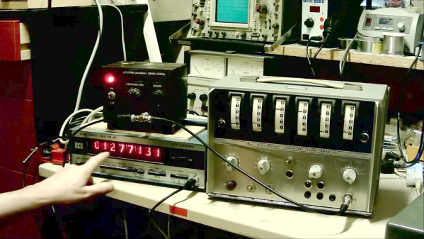
With regard to retro test gear, one’s thoughts tend to those Nixie-adorned instruments of yore, or the boat-anchor oscilloscopes that came with their own carts simply because there was no other way to move the things. But there were other looks for test gear back in the day, as this frequency counter with a readout using moving-coil meters shows.
We have to admit to never seeing anything like [Charles Ouweland]’s Van Der Heem 9908 electronic counter before. The Netherlands-based company, which was later acquired by Philips, built this six-digit, 1-MHz counter sometime in the 1950s. The display uses six separate edge-mounted panel meters numbered 0 through 9 to show the frequency of the incoming signal. The video below has a demo of what the instrument can do; we don’t know if it was restored at some point, but it still works and it’s actually pretty accurate. Later in the video, he gives a tour of the insides, which is the real treat — the case opens like a briefcase and contains over 20 separate PCBs with a bunch of germanium transistors, all stitched together with point-to-point wiring.
We appreciate the look inside this unique piece of test equipment history. It almost seems like something that would have been on the bench while this Apollo-era IO tester was being prototyped.
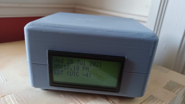
Even the most punctual among us are content to synchronize their clocks to external time sources like navigation satellite constellations, network time servers, frequency-controlled AC mains, or signals broadcast by radio stations such as WWV, CHU, and DFC77 — but not [zaphod]. After building a couple of more traditional clocks over the years, he set his sights on making a completely isolated digital clock that doesn’t rely on external synchronization (well, except to initialize the time at first power-up).
The accuracy goal he set for himself was that of a Casio F-91W wristwatch, which is specified to maintain +/- 30 seconds per month (about 12 ppm). At the heart of the design is an oven-controlled crystal oscillator whose stability is in the single-digits parts-per-billion.
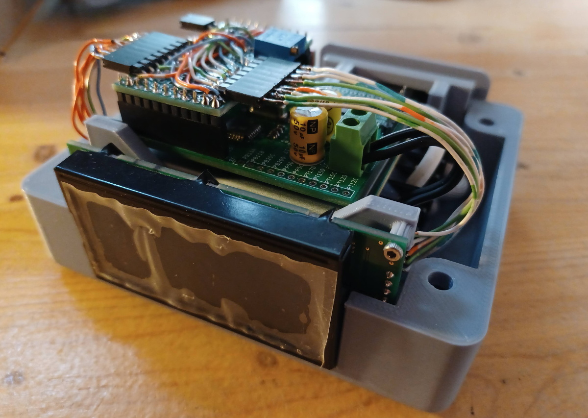
The counter chain that accumulates the time is implemented in an FPGA — admittedly overkill, but [zaphod] wanted to learn FPGA programming for this project as well. An ATmega328 drives the display and does other bookkeeping tasks. The whole design is partitioned into three PCBs which fit inside a custom 3D-printed case.
[zaphod] does a thorough job documenting his build, including the bugs and failures along the way. We like the honest summary he wrote at the project’s conclusion, noting things that could be improved or should have been done differently. Be sure to check out the GitHub repository, where all the source code and PCB design files are posted. How accurate is your wristwatch, if you even wear one anymore?
The laptop I’m using, found for 50 bucks in the junk bins of Akihabara has a CPU that runs at 2.53GHz. Two billion five hundred and thirty million times every second electrons systematically briefly pulse. To the human mind this is unimaginable, yet two hundred years ago humanity had no knowledge of electrical oscillations at all.
There were clear natural sources of oscillation of course, the sun perhaps the clearest of all. The Pythagoreans first proposed that the earth’s rotation caused the suns daily cycle. Their system was more esoteric and complex than the truth as we now know it and included a postulated Counter-Earth, lying unseen behind a central fire. Regardless of the errors their theory contained, a central link was made between rotation and oscillation.
And rotational motion was exploited in early electrical oscillators. Both alternators, similar to those in use today, and more esoteric devices like the interrupter. Developed by Charles Page in 1838, the interrupter used rocking or rotational motion to dip a wire into a mercury bath periodically breaking a circuit to produce a simple oscillation.
As we progressed toward industrial electrical generators, alternating current became common. But higher and higher frequencies were also required for radio transmitters. The first transmitters had used spark gaps. These simple transmitters used a DC supply to charge a capacitor until it reached the breakdown voltage of the gap between two pieces of wire. The electricity then ionized the air molecules in the gap. Thus allowing current to flow, quickly discharging the capacitor. The capacitor charged again, allowing the process to repeat.
As you can see and hear in the video above spark gaps produce a noisy, far from sinusoidal output. So for more efficient oscillations, engineers again resorted to rotation.
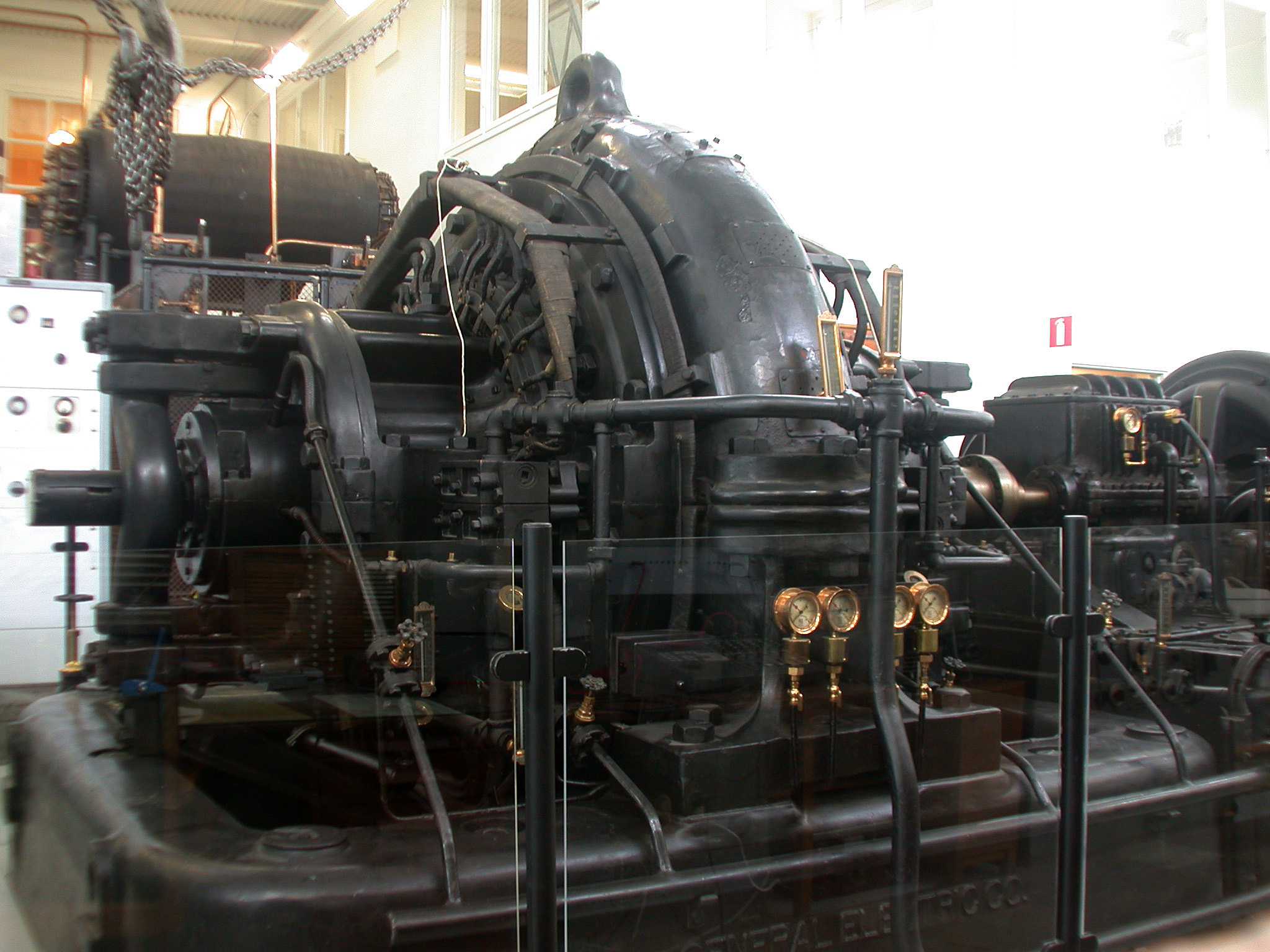
The Alexanderson alternator uses a wheel on which hundreds of slots are cut. This wheel is placed between two coils. One coil, powered by a direct current, produces a magnetic field inducing a current in the second. The slotted disc, periodically cutting this field, produces an alternating current. Alexanderson alternators were used to generate frequencies of 15 to 30 KHz, mostly for naval applications. Amazingly one Alexanderson alternator remained in service until 1996, and is still kept in working condition.
A similar principal was used in the Hammond organ. You may not know the name, but you’ll recognize the sound of this early electronic instrument:
The Hammond organ used a series of tone wheels and pickups. The pickups consist of a coil and magnet. In order to produce a tone the pickup is pushed toward a rotating wheel which has bumps on its surface. These are similar to the slots of the Alexanderson Alternator, and effectively modulate the field between the magnet and the coil to produce a tone.
Amplifying the Oscillation
The operation of a tank circuit (from wikipedia)
So far we have purely relied on electromechanical techniques, however amplification is key to all modern oscillators, for which of course you require active devices. The simplest of these uses an inductor and capacitor to form a tank circuit. In a tank circuit energy sloshes back and forth between an inductor and capacitor. Without amplification, losses will cause the oscillation to quickly die out. However by introducing amplification (such as in the Colpitts oscillator) the process can be kept going indefinitely.
Oscillator stability is important in many applications such as radio transmission. Better oscillators allow transmissions to be packed more closely on the spectrum without fear that they might drift and overlap. So the quest for better, more stable oscillators continued. Thus the crystal oscillator was discovered, and productionized. This was a monumental effort.
Producing Crystal Oscillators
The video below shows a typical process used in the 1940s for the production of crystal oscillators:
Natural quartz crystals mined in Brazil were shipped to the US, and processed. I counted a total of 13 non-trivial machining/etching steps and 16 measurement steps (including rigorous quality control). Many of these quite advanced, such as the alignment of the crystal under an X-Ray using a technique similar to X-Ray crystalography.
These days our crystal oscillator production process is more advanced. Since the 1970s crystal oscillators have been fabricated in a photolithographic process. In order to further stabilize the crystal additional techniques such as temperature compensation (TCXO) or operating the crystal at a temperature controlled by the use of a heating element (OCXO) have been employed. For most applications this has proved accurate enough… Not accurate enough however for the timenuts.
Timenuts Use Atoms
Typical timenut wearing atomic wristwatch
For timenuts there is no “accurate enough”. These hackers strive to create the most accurate timing systems they can, which all of course rely on the most accurate oscillator they can devise.
Many timenuts rely on atomic clocks to make their measurements. Atomic clocks are an order of magnitude more precise than even the best temperature controlled crystal oscillators.
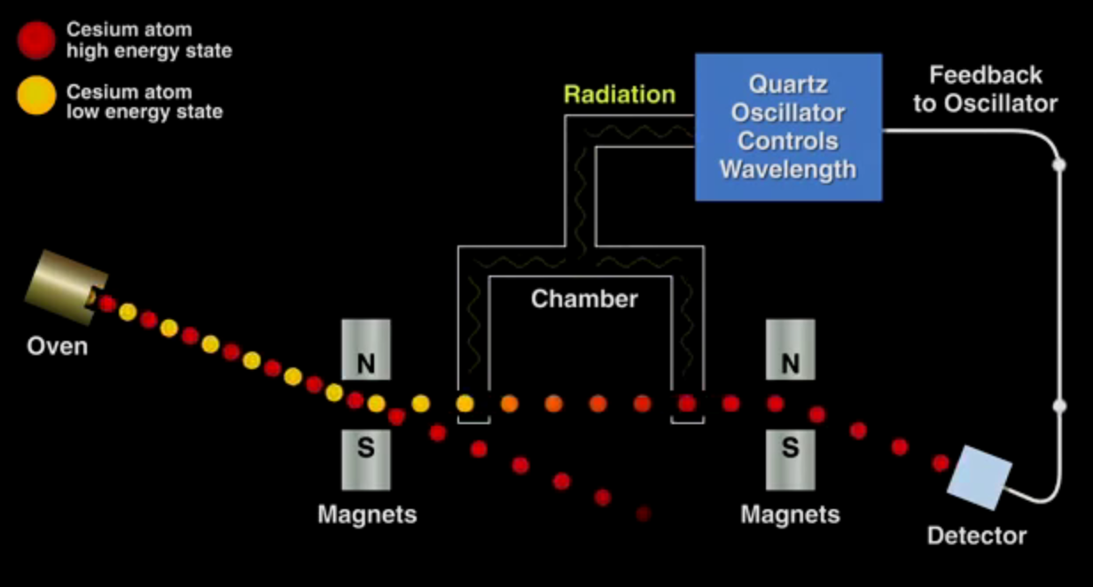
Bill Hammack has a great video describing the operation of a cesium beam oscillator. The fundamental process is shown in the image below. The crux is that cesium gas exists in two energy states, which can be separated under a magnetic field. The low energy atoms are exposed to a radiation source, the wavelength of which is determined by a crystal oscillator. Only a wavelength of exactly 9,192,631,770Hz will convert the low energy cesium atoms to the high energy form. The high energy atoms are directed toward a detector, the output of which is used to discipline the crystal oscillator, such that if the frequency of the oscillator drifts and the cesium atoms are no longer directed toward the detector its output is nudged toward the correct value. Thus a basic physical constant is used to calibrate the atomic clock.
The basic operating principle of a cesium atomic clock
While cesium standards are the most accurate oscillators known, Rubidium oscillators (another “atomic” clock) also provide an accurate and relatively cheap option for many timenuts. The price of these oscillators has been driven down due to volume production for the telecoms industry (they are key to GSM and other mobile radio systems) and they are now readily available on eBay.
With accurate time pieces in hand timenuts have performed a number of interesting experiments. To my mind the most interesting of these is measuring time differences due to relativistic effects. As is the case with one timenut who took his family and a car full of atomic clocks up Mt. Rainier for the weekend. When he returned he was able to measure a 20 nanosecond difference between the clocks he took on the trip and those he left at home. This time dilation effect was almost exactly as predicted by the theory of relativity. An impressive result and an amazing family outing!
It’s amazing to think that when Einstein proposed the theory of special relatively in 1905, even primitive crystal oscillators would not have been available. Spark gap, and Alexanderson alternators would still have been in everyday use. I doubt he could imagine that one day the fruits of his theory would be confirmed by one man, on a road trip with his kids as a weekend hobby project. Hackers of the world, rejoice.
The HP 5328 Universal Counter is all the counter you’ll ever need. It’s rugged, does its job well, and like all old HP gear, keeps on going. When it breaks, though, that’s a problem.
[Tom] had an 5328 Universal Counter with a broken Oven Controlled Crystal Oscillator. This is the HP 10544 OCXO and replacements are pretty spendy. Instead of buying a vintage unit, [Tom] decided to make a replacement.
The OXCO in the HP 5328 is just an option. If the frequency counter has this option installed, a 30-pin edge connector in the counter is stuffed with a little PCB. Like all HP gear, the schematics are readily available, and the original OXCO can be quickly reverse engineered.
The design of the replacement is fairly straightforward. A 10MHz OXCO from Oscilloquartz is used, powered from the 28V rail in the 5328 with a simple switching regulator. Apart from that, it’s just an inverter to get the logic levels correct, and a small, multi-turn pot to calibrate the new OXCO. The completed unit is much smaller than the original OXCO option, so it can be plugged directly into the 30-pin card edge slot, leaving the gigantic standoff inside the frequency counter as a reminder of days gone by.
The crystals you’ll find attached to microcontrollers or RTCs are usually accurate to 100 parts per million at most, but that still means if you’re using one of these crystals as a clock’s time base, you could lose or gain a second per day. For more accuracy without an atomic clock, a good solution is an oven controlled crystal oscillator – basically, a temperature controlled crystal. It’s not hard to build one, and as [Roman] demonstrates, can be built with a transistor and a few resistors.
The heating element for this OCXO are just a few resistors placed right on the can of a crystal. A thermistor senses the heat, and with more negative feedback than the Hackaday comments section, takes care of regulating the crystal’s temperature. A trimpot is used for calibrating the temperature, but once everything is working that can be replaced with a fixed resistor.
This deadbugged circuitry is then potted in five minute epoxy. That’s a bit unconventional as far as thermal management goes, but the results speak for themselves: [Roman] can get a clock with this circuit accurate to a few seconds per year.

 This GPS Disciplined Oscillator (GPSDO) project uses a Piezo 2940210 10 MHz crystal oscillator which is both oven-controlled (OCXO) and voltage-controlled (VCXO). The GPSDO takes the precision 1 Pulse-Per-Second (PPS) GPS signal and uses it to adjust the 10 MHz crystal oscillator until it repeatedly produces 10,000,000 cycles within one second.