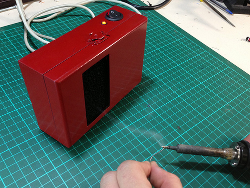
Our homemade shop tools rarely reach this level of finished quality. We probably would have stopped with assembly of this USB powered fume extractor. But [X2jiggy] went for style points by adding a coat of paint.
There are several nice features included in his build. He wanted it to be very easy to power the device so he settled on the 5V USB standard. But a PC fan running at 5V won’t pull much air. He used a boost converter board to ramp that up to 12V. The enclosure is a wooden hobby box. He drilled mounting holes and an airflow opening in the bottom of the box for the fan. The lid of the box has a rectangular opening which accepts a carbon filter meant for aquariums. The rocker switch and LED seen above are also nice touches, but not strictly necessary if you build this for yourself.
We’re still in the habit of gently blowing the fumes away from us as we solder. So the question is, will this device save us from a gruesome disease down the road, or is it mostly to capture the odor of the solder fumes?
Looking for a more permanent setup? You should build a solder hood for your workbench.
Continue reading “USB Fume Extractor Takes Stink Out Of Soldering Sessions”
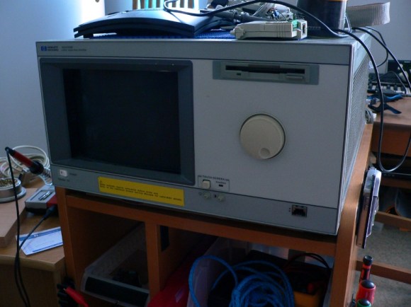

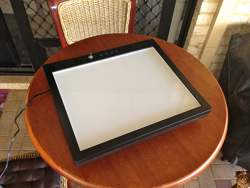 [x2jiggy] was given a non-functioning LCD monitor. He made a small effort to trouble-shoot its inability to display anything on the screen but couldn’t get it working again. When that failed he decided to