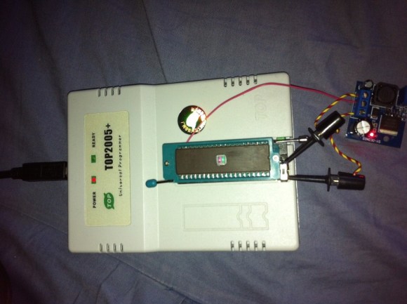
EagleUp Pulls Your PCBs Into SketchUp

[Karl] wrote in to tell us about a software package called EagleUp that will import your Eagle CAD PCB designs into Google SketchUp. It bridges the gap between the two using the open source image processing software ImageMagick.

As you can see above, you’ll end up with a beautifully rendered 3D model of your hardware. This is a wonderful way to make sure that your enclosure designs are going to work without needing to wait for the PCBs to arrive from the fab house. It is available for Windows, OSX and Linux (although the last time we tried to run Sketchup under Wine nothing good came of it — perhaps it’s time to try again).

In [Karl’s] case, he’s working on an Arduino compatible board based around the Xmega. He mentions that EagleUp is a great way to get an idea of how component placement will end up, and to see if the silk screen layer is going to turn out well or not. Here’s a link to one of his test designs.

Solder Reflow Toaster Oven

[Sebastian] needed a small solder oven so he bought himself a small toaster oven (Spanish, Google Translate). It’s not the kind of thing we’d make our breakfast in now, but for soldering it’s a very nice oven.

After a little bit of research on Google, [Sebastian] discovered that the best technique when dealing with reflow ovens and solder paste is following a specific temperature curve. Ideally, Tin/Lead solder needs to preheat from room temperature to 150 degrees C, then level off so the flux can activate. After that, a quick jaunt above 183 degrees C makes the solder flow. To get his toaster working optimally, [Sebastian] stuck a thermistor in the toaster and measured the temperature profiles of different ‘modes.’

The correct temperature curve was calculated using different heater elements and [Sebastian] was off to the races. He did have a few problems on his first few boards – solder bridging, mostly – but that’s not the fault of the oven. An LCD display (translate) was added recently so accurate real-time temperature monitoring is available.

FT-2232 Bridges Python And I2C/SPI

You might already have the hardware on hand to easily interface I2C and SPI devices with Python scripts on your computer. The board seen above is an FT-2232 breakout board. These chips are often used to facilitate JTAG programming via USB, but they have other features that might be useful to you as well. The chip has a Multi-Protocol Synchronous Serial Engine (MPSSE) which can speak the I2C and SPI protocols, you just need to know how to active them in your code.

[Craig] makes this easy with his MPSSE Python wrapper. Simply install his module, and you’ll be able to import all the commands you need. He demonstrates reading the data out of a 1 MB SPI flash memory chip. This could be used for a lot more, including debugging peripherals à la the Bus Pirate, or reprogramming chips to add to your projects (we’re thinking font arrays and sprites for displays, or look-up tables).

If you’re not aware, these FTDI chips were the go-to for USB support for a long time. We’ve got a guide for bit-banging using this hardware. Lately more chips have become available with USB hardware built-in. They’re quite useful and cost-effective, especially with the availability of open-source stacks like the LUFA project.

Rebuilding A Bridgeport Mill

It looks like the Internet’s resident steampunker is moving up a century or two. [Jake Von Slatt] rebuilt the CNC portion of a Bridgeport Series II mill so it can interface with a computer. It’s a feat even more impressive than moving the mill into [Jake]’s garage.

The first step of the build was tearing out the BOSS 5 industrial microcomputer and replacing it with a Win XP laptop running ArtSoft’s Mach 3. This allows G-code to be displayed directly on the screen. The old power supply for the mill did give [Jake] a few problems. The Gecko stepper drivers that replace the old electronics couldn’t handle the voltage of the old power supply. That can be dealt with by opening the transformer and removing a few turns of wire.

[Jake] has been sending in a few of his hacks as of late, so it’s good to see Hack a Day has another fan, especially one of [Mr. Von Slatt]’s caliber. There is a problem with the mill modifications though – [Jake] hasn’t figured out how to program it. If any HaD readers would like to chime in on the best way to program G-code for the mill, feel free to leave a message in the comments.

Adding RS232 To A Multimeter The Hard Way

You might want to store information from a multimeter to be graphed over time. This comes with pretty much all of the high-end professional models. But if you buy a super cheap meter you can bet this isn’t an option. [Jazzzzzz] has found a way to pull the data from a $4 meter via RS232. It’s not impossible, but we definitely think he’s doing it the hard way. That’s because he’s not just tapping into a dormant feature. He’s actually adding a microcontroller to sample the data and push it via the RS232 protocol.

On the bright side, this is easier than building a multimeter from scratch. The sampling circuits are still being used, with a PIC 16F688 intercepting the signals as they enter the stock microcontroller. The signal he was after comes into the chip on just one pin, but to get the readings right on the PIC he had to use an OpAmp. That’s only part of the puzzle as he also needed a way to tell what the selector switch was set at. In the end, adding a potentiometer and reading its value let him calculate the position.

[Thanks Karl]

Talking Digital Calipers Make Engineering More Accessible

talking-digital-calipers

The team over at NerdKits recently put together a device aimed to help make the process of measuring things more accessible to those with disabilities. [Terry Garrett] is a Mechanical Engineering student, and as anyone who is in the field knows, it’s a discipline which requires taking tons of measurements. Since [Terry] cannot see he was often asking classmates to assist in measuring items during labs, but when he got a job at a nearby design studio, he knew he would have to find a way to take those measurements on his own.

Enter NerdKits.

[Humberto] wrote in to share how he and his team built a set of talking digital calipers to assist [Terry] in his daily tasks. They based the design off a previous project they worked on, getting digital readout data from a set of calipers. The DRO information is fed into an ATmega382p, which pieces together pre-recorded sound bites to announce the size of the object being measured.

As you can see in the video below, the system looks to work very well, and [Terry] is quite pleased with his new talking tool. We love seeing these sorts of hacks, because they truly make a difference in people’s lives – excellent job!

Continue reading “Talking Digital Calipers Make Engineering More Accessible”

This Panavise Jr. Speed Winder Should Be In Every Maker’s Toolbox

panavise-jr-power-winder

Like many makers, [Chris] has a Panavise Jr. on his workbench that he uses for just about everything. The tiny vise is great for all sorts of tasks, and is often considered an indispensable tool. The only problem with the vise is the amount of time it takes to open and close the thing.

[Chris] estimates that it takes somewhere between 2 and 3 million turns of the crank to move the vise’s jaws from fully open to the fully closed position. He figured that his drill is far better at mindlessly turning circles than he is, so he sat down and designed a bit in Google Sketchup to spin the vise’s crank knob.

He fired up his MakerBot and printed out his first “Speed Winder” drill bit. It was decent, but he thought it could be better. After a handful of revisions, he was finally happy with the results. He says it works great, and has posted the model on Thingiverse so that everyone can print one of their own.

Continue reading to see how [Chris] created the bit along with how much time this thing saves him. Continue reading “This Panavise Jr. Speed Winder Should Be In Every Maker’s Toolbox”