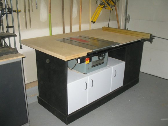
They May Be For Developing Countries, But We Want A Concrete Lathe

At the 2009 Ghana Maker Faire, [Pat Delany] met a young carpentry student that saved for three months to buy a cheap Chinese wood plane. He was confounded by this distribution of resources, so [Pat] created the Concrete Lathe project that aims to get useful machine tools out to where they’re needed most.

The idea for concrete machine tools came out of the US involvement in World War I. America had been staunchly isolationist before committing to the war, and production of arms did not match the needed output. A man named L.I. Yeomans came up with the idea of building concrete lathes to produce artillery shells for the war effort.

Of course, the concrete lathe project is a bit more peaceful in its intentions. The concrete lathe is meant to be a cheap machine tool for developing nations. Both the concrete lathe and the Multimachine are meant to be built cheaply using scrap materials, reduce training time for machinists, and create other machine tools in a Reprap-like biological distribution.

There’s a ton of documentation on the concrete lathe wiki like the bed instructions torn from the pages of Ikea instructions, and the thread follower. While they’re still a lot of work and testing to be done, giving some manufacturing capability to those who need it most is a pretty noble cause.

Thanks [Rob] for sending this one in.

DIY Breadboard Modules For Easy Prototyping

[Rajendra] got tired of building the same basic circuits time and again on the breadboard. He decided to build some simple, modular circuits on protoboard and make them easy to interface with the breadboard. As you can see, he ended up with seven modules that make prototyping faster and easier.

At first glance some might not seem all that beneficial. For instance, making a board for an 18-pin PIC microcontroller into a single-in-line form factor would seem like you’re actually wasting breadboard space when compared to the DIL package of the chip. But consider that the oscillator and its capacitors, reset button, and programming header are also on the breakout board and will not have to be built in place. There are also several I/O boards, one with five buttons, another with an LED bar graph, and a set of LEDs with a SIL resistor package on-board. These modules can be plugged into a breadboard and wired up with jumper wires, or connected directly to the same rows as the microcontroller module.

How To Decode IR Remote Control Signals With Your PICkit 2

[SpiralBrain] needed to figure out the coding scheme used by an IR remote control so that he could use it with his own project. He built an IR receiver board for the PICkit 2 and figured out how to use some of the Microchip software to measure the timing of the incoming signal.

The hardware’s dead simple; a 38 kHz IR receiver does the heavy lifting by filtering out errant infrared light. When it does detect a signal with the correct frequency the output pin drives the base of a transistor to toggle the input pin on the PICkit 2. The breakout board has a pin header which makes it a snap to detach and store for later use. The PICkit 2 Logic Tool software captures this input, by setting the correct pin as a trigger and choosing a 10 kHz sample rate.

As we discussed in our PIC programming with Linux tutorial, the PICkit 2 really is far superior to its replacement, the PICkit 3. [SpiralBrain] mentions that it is more versatile than the newer version but doesn’t go so far as to tell us whether you can use this hardware with the PICkit 3 or not.

Improvised Metal Lathe

[McKGyver] needed a few parts manufactured. Instead of going the normal route – finding friends with machine tools or paying a machine shop, he improvised a rudimentary metal lathe.

As much as we love 3D printers, they’re not the be-all, end-all solution for everything. Sometimes, you need to get a little dirty and do it the old-fashioned way. [McKGyver] needed a way to produce aluminum shaft couplers to join stepper motors to lead screws. A 1940s grinding wheel was used for the headstock. Since [McKGyver] only needed couplers of one size, he made a jig out of wood to attach the aluminum blanks to the spindle. A drill and a focuser from a photographic enlarger makes up the tailstock of the improvised lathe. The use of a camera focuser is pretty clever. Unless the equipment has been damaged, it’s guaranteed to move in a straight line. A small laser was used to align the drill.

The finished couplers were concentric to 0.005″. A ‘passable precision’ for his application, and a clever build that doesn’t involve moving a thousand pound South Bend lathe.

[Dino] Builds A Simple Non-contact Voltage Detector

homemade_voltage_detector

[Dino] is back with another installment of his Hack a Week series, and in this episode he is taking on what he promises will be the last transistor-based project – at least for a little while.

In the video embedded below, he shows off a homemade voltage detector circuit that he constructed using a trio of BC547 NPN transistors. The circuit is pretty simple though very useful all the same. At one end, the device has a small copper strip, which is connected to the base of the first transistor. The emitter of that transistor is daisy chained to the base of the second transistor and so on, until reaching the indicator LED.

As noted by one of [Dino’s] viewers, the circuit functions as follows:

“The front end copper strip forms one side of a capacitor, and then when you bring it near a voltage potential a super tiny current flows between air dielectric of the “cap”. This is mega amplified with the high gain BC547′s and viola, the LED lights up.”

Since the small bit of current is amplified many times over, the LED lights up even when very small voltages are present. While we might not necessarily trust our lives to [Dino’s] voltage detector, we’re sure it would come in handy now and again.

Continue reading “[Dino] Builds A Simple Non-contact Voltage Detector”

PIC LC Meter Improvements Add Li-Ion Battery And Charging Circuitry

[Trax] needed an LC meter and decided to use a tried-and-true design to build his own. The only problem was that he didn’t want to be tied to a bench supply or power outlet, which meant a bit of auxiliary design was in order. What he came up with is the battery-powered LC meter you see above.

The core of the original [Phil Rice] design remains the same, with slight modifications to drive a different model of character LCD. The code is mostly unchanged, but some calibration routines became necessary after [Marko] noticed bugs in the behavior after power cycling. Now the device will perform what amounts to a hardware reset about 700ms after powering on or changing between inductance and capacitance measuring functions. The project box is quite small, and to get everything to fit [Marko] sourced the Lithium Ion battery from a Bluetooth headset. He needs 5V for the LCD screen so he used a TPS61222 boost converter. To top off the battery he’s included a MAX1811 single-cell Li-ion charger, which has a couple of status LEDs visible through the case as seen above.

[Thanks Marko]

8 Breadboard Hacks To Make Life Easier

If you like messing around with electronics, one of the best tools you can have on hand is a solderless breaboard. These handy little chunks of plastic just let you “plug n play” so you can quickly develop a circuit before committing it to solder and fiberglass. Handy as they are, they do have their downsides such as:  stuff not fitting, split up power rails, running out of jumpers or just taming what can quickly become a birds nest of a mess.

Luckily the folks over at [Proto Stack] have published a handy article giving us 8 Breadboard Hacks. While anyone that has used breadboads for any length of time will have probably figured most of these out, its still good knowledge for any newcomers to the sometimes aggravating world of plastic and jumpers.

Also we know there are more hacks you can do to make your lives easier and would love to hear them in the comments.