Homebrew Heat Gun From Scrounged Parts

A Hack a Day reader needed a tool to solder a lot of SMD parts, so he built a DIY heat gun, and we’re impressed with the results.

After trawling the internet looking for ideas for his heat gun, [MRGATZ85] found that most builds used the ceramic element from cheap soldering irons. Experiments in this direction didn’t go very well because the ceramic element in these irons tends to fall apart very easily. In a moment of inspiration, [MRGATZ85] realized he had an old vaporizer lying around and decided to take it apart. To his surprise, the vaporizer element was a great size, self-contained, and most importantly free. After fabricating a case out of high-temperature foam, aerosol cans, and deadbolt parts, [MRGATS85] was left with a very nice build.

Aside from SMD work, a heatgun can be a very valuable tool for PCB stripping and being used for solder reflow. We’re a little surprised we haven’t seen a homebrew heat gun in quite a while. Even though the element is surrounded by high-temperature foam, the gun still gets a little hot to the touch. We’re hoping that will eventually be under control; it’s a very useful build otherwise.

Check out the image gallery, or the video demo after the break.

Continue reading “Homebrew Heat Gun From Scrounged Parts”

Adjustable Voltage And Polarity Tester

polarity_tester

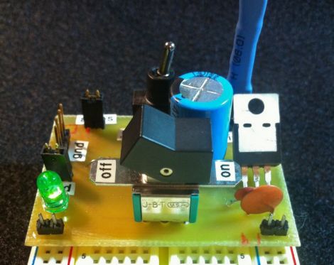
Instructables user [Rudolf] wrote in to share a handy little tool he created with ham radio operators in mind. Now and again, he found himself connecting to an unknown power supply, and rather than blow out all his expensive radio gear, he decided to put together a simple polarity and voltage tester that can be easily carried out in the field.

The tester features a pair of powerpole connectors, which are used quite often for connecting HAM gear. A PIC12F675 runs the show, acting as an adjustable comparator for detecting voltage levels. By default, his probe glows amber when the supply voltage is below 11.5V, turning green when the supply is between 11.5V and 15V. When the detected voltage is too high, the built-in LED glows a bright red. When the polarity is reversed, the LED flashes red regardless of the supply voltage.

All of these trigger levels can be set in the PIC’s code, which [Rudolf] is kind enough to include on his page, along with schematics for making your own.

3D Printer Looks Factory Made

[Richard Sum] came up with a great looking 3D printer and put his project up as a campaign on IndieGoGo.

[Richard]’s ‘SUMPOD’ is based off the reprap like a lot of other 3D printers, but the SUMPOD has a look of professionalism to it; the printer looks like something that would come from a factory. We think a lot of thought went into the design and fabrication of this printer.

The specs of the machine aren’t too bad either. It’s build area is 150x150x100 mm, or nearly 2 inches than the Makerbot Thing-O-Matic. We asked [Richard] about the drive system of the machine, and he told us there is a linear bearing/belt setup for the x and y axes with a screw drive for the z axis. The electronics are standard NEMA 17 motors and reprap RAMPS fare, so everything electrical is tried and true.

[Richard] plans on adding a Dremel attachment for pcb and lithophane milling. We hope that some design files of the SUMPOD released, but in the mean time we’re really looking forward to seeing the progress of this project.

Autodesk Enters The Hobby Market

Autodesk aims to enter the hobby market with its offering of Autodesk 123d. If you’ve ever been spoiled by a nice CAD suite like Solidworks, Pro-E, or Inventor it becomes readily apparent that the free offerings don’t come anywhere close. At first Autodesk 123d seems to be entirely a Google Sketchup clone, and in some ways it is. Though, after a bit more exploring, the software offers some pretty advanced features, such as assemblies and constraints . All worries about it being windows only and closed source aside, it’s pretty cool that a big name in the CAD industry is taking a look at the hobby market, and overall it is worth testing out to see if it fits into your toolbox.
Continue reading “Autodesk Enters The Hobby Market”

Pick And Place At Home

diy_pick_and_place

[Erv’] wrote in to share a manual pick and place he recently constructed. He builds a lot of circuits using SMD parts, and after looking at commercial pick and place systems, he decided it would be far cheaper to build his own. Using some components he had sitting around the house, along with a few store-bought pieces, he put the pick and place together for about $50, which is pretty cheap when you think about it.

The base is made from wood he had left over from another project, which has a sliding rail and a movable arm rest built into it. A rotating TV stand is used to hold workpieces, allowing PCBs to be repositioned at will while parts are being laid out. A square furniture leg is used as a support arm, holding the pick and place vacuum pen in place at the end of a small accordion hinge. As in most DIY pick and place installations, a small aquarium pump has been used to provide the suction needed to pick up SMD parts.

It’s a great build with plenty of useful features, and comes in far cheaper than any commercial system you’ll find out there.

Designing And Building A Bench Supply

[Scott’s] been digging around the back issues of the Internet to find this project. He blew the dust off and sent us a link to an article that traverses the design and build process of a bench power supply.

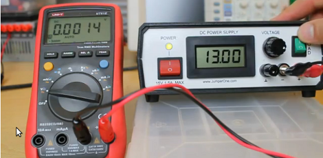
[Guido Socher] does an excellent job of presenting his bench supply project. So many others show of the final product, but he has gone out of his way to make sure we understand the design principles that went into it. He starts off by talking about the simplest possible supply design: a transistor and Zener diode which generates a reference voltage. He goes on to discuss the problems with this simplified circuit and how to address them, covering the gotchas that pop up at each step in the process.

Once he designed the circuit and laid out some boards he began building an enclosure. We love his tip about using a stick pin and an unpopulated through-hole PCB to mark button locations on the front bezel of the case. The final design is shown above, and includes a laptop brick to translate mains power into a 24V 3A DC feed for his custom circuitry.

Building A One-ton Linear Servo

one_ton_servo_jack

A while back, [Windell] from Evil Mad Scientist Laboratories wrote up an article for Make Magazine detailing how he built a one-ton, servo-controlled scissor jack for under $100. He dropped us a line to let us know that the project details have been released for free at Make Projects, so we stopped by to take a look.

The project starts out by pulling apart an electronic scissor jack to get access to the solder pads for the up and down buttons. Once wires are added there, a servo is the next victim. [Windell] recommends using an old servo with a busted motor, but you can use a good one just the same. The servo’s pots are replaced with 10 turn pots, and then wired up to a controller board, to which the jack is also connected. Then, to provide feedback to the servo, a string is looped around the top of the jack, which is used to turn the pots added in the previous step.

[Windell] says that the setup works quite well, though we imagine the duty cycle might be a bit short before adjustments are required. Regardless, it’s a quick way to get a heavy load lifted with servo precision.