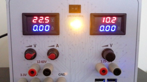
If there’s one thing that for decades of desktop PCs have given us, it’s a seemingly endless supply of relatively capable power supplies. If you need 5 volts or 12 volts at a respectable current they’re extremely useful, so quite a few people have used them as bench power supplies. Some of these builds box up the mess of wires into a set of more useful connectors, but [Joao Pinheiro] has taken his to the next level with a very neat 3D printed case and a set of variable switching regulators to make a variable bench supply with a top voltage of 60 volts.
In many ways it’s a straightforward wiring job to build, but there’s an unexpected power resistor involved. It’s sinking the 5 volt line, and we’re guessing that some current is required here for the PC power supply to run reliably. The thought of a high power resistor dumping heat into a 3D printed case leads us to expect that things might become a little melty though.
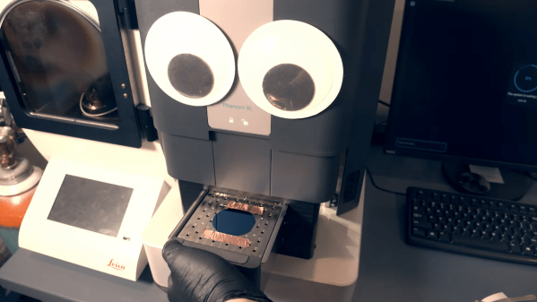
Over the past few years we’ve seen several impressive projects where people try to manufacture integrated circuits using hobbyist tools. One of the most complex parts of this process is lithography: the step in which shapes are drawn onto a silicon wafer. There are several ways to do this, all of them rather complicated, but [Zachary Tong] over at Breaking Taps has managed to make one of them work quite well. He shares the results of his electron-beam lithography experiments in his latest video (embedded below).
In e-beam lithography, or EBL, shapes are drawn onto a wafer using an electron beam in a vacuum chamber. This is a slow process compared to optical lithography, as used in mass production, but it is reasonably simple and very flexible. [Zach] decided to use his electron microscope as an e-beam litho machine; although not designed for lithography, it has the same basic components as a real EBL machine and can act as a substitute with a bit of software tweaking.
[Zach] also has an atomic force microscope, which he used to make these beautiful images.The first step is to coat a wafer with a layer of e-beam resist. [Zach] used PMMA, commonly known as acrylic plastic, and applied it using spin coating after dissolving it in anisole. He then placed the wafer into the electron microscope and used it to scan an image. The image was then developed by rinsing the wafer in cold isopropyl alcohol.
[Zach] explains the whole process in detail in his video, including how he tuned all the parameters like resist thickness, beam strength, exposure time and development time, as well as the software tricks needed to persuade the microscope to function as a litho machine. In his best runs he managed to draw lines with a width of about 100 nanometers, which is seriously impressive for such a relatively simple setup.
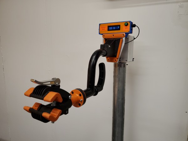
If you’ve ever done maintenance or repair work on your bicycle, you’ll know that positioning a bike in your workshop isn’t trivial. You can use your bike’s kickstand, or lean it against a wall, but then you can’t work on the wheels. You can place it upside-down, but then the shifters and brake levers are hard to reach. You can hang it from the ceiling, but then you first need to install hooks and cables in hard-to-reach places. Ideally you’d want to have one of those standing clamp systems that the pros use, but their price is typically beyond a hobbyist’s budget.
Or at least, that’s how it used to be. As [Dane Kouttron] discovered, a simple wall-mounted bike clamp can be had for as little as $35 on eBay, and can easily be converted into a smart mobile repair stand. [Dane] fashioned an adjustable stand from some steel pipes he had lying around, and 3D-printed an adapter bracket to mount the bike clamp on it. This worked fine, but why stop at a simple clamp when you can expand it with, say, an integrated scale to weigh your bikes while you work on them? Continue reading “DIY Repair Stand Holds Your Bike And Weighs It”→
A benchtop power supply is a key thing to have for any aspiring electronics hacker. While you can always buy one, plenty of us have old computer PSUs lying around that could do a fine job themselves. [Frugha] decided to whip up a neat 3D-printed design for converting any ATX PSU into a usable bench unit.
The design features banana plugs outputting +12V, -12V, +5V, and +3.3V, with all outputs appropriately fused for safety. There’s also a fused stepdown converter used to supply variable voltages as needed. Its original trimpot was replaced with a multi-turn pot for ease of control. To make everything work, a load resistor on the 5V circuit makes the power supply think it’s hooked up to a motherboard. It’s all wrapped up in a neat slant-sided 3D-printed case that fits onto the ATX power supply itself.
The result is a neat and tidy power supply built out of readily-available components. We particularly like the addition of the stepdown converter – most ATX-based projects don’t offer variable output, which can nonetheless come in handy.
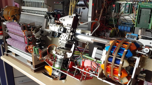
Weaving is one of the oldest crafts in the world, and was also among the first to be automated: the Industrial Revolution was in large part driven by developments in loom technology. [Roger de Meester] decided to recreate that part of the industry’s history, in a way, by building his own desktop-sized, fully automatic loom. After a long career in the textiles industry he’s quite the expert when it comes to weaving, and as you’ll see he’s also an expert machine builder.
[Roger]’s loom is of a specific type called a dobby loom, which means that the vertical threads (the warp) can be moved up and down in various ways to create different patterns in the fabric. The horizontal wires (the weft) are created by a shuttle moving left and right, carrying a bobbin that unspools as it travels. A comb-shaped plate (the reed) then fixes the fresh weft in its place. [Roger]’s videos (embedded below) clearly show this mechanism in action, as well as the loom’s overall design.
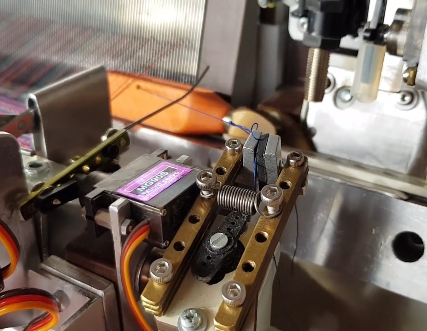
A clamp hold the end of the weft as the shuttle starts its run
The 3D printed shuttle is moved back and forth through the warp by a belt-driven system that grabs the magnetic end of the shuttle. Revolving storage drums on either side of the machine enable the use of different thread colors for each shuttle run. Shuttles are exchanged by a robotic arm that picks them up and places them onto the track; there’s a clamp that grabs the end of the thread as the shuttle starts its run, and a wire cutter to detach it when the shuttle is up for replacement.
This intricate mechanical dance is controlled by a set of Arduino Megas and Nanos. They drive all the servos, DC motors, and steppers while reading out an array of sensors and switches. The system can even detect several faults: the weft is checked for proper tension after each cycle, shuttles with empty bobbins are automatically discarded, while a laser keeps an eye on the warp to ensure none of the threads have snapped.
The entire machine is of [Roger]’s own design; apart from 3D-printed and CNC-machined parts, he also re-used components from various pieces of discarded machinery. His ultimate purpose is to use this machine to make specialized fabrics for medical or industrial use: for example, it can use conductive threads to make fabrics with built-in sensors.
Although this isn’t the first DIY automatic loom we’ve featured, it’s definitely the most advanced. Previous examples, like this 3D-printed miniature version or this neat computer-controlled one can’t really compare to [Roger]’s 26 cm reed width and wide customizability. If you prefer to keep things a bit simpler, you can also use a 3D-printer to directly print certain fabrics.
There’s no shame in admitting you’ve been burned by a cheapo USB cable — ever since some bean counter realized there was a few cents to be saved by producing “power only” USB cables, no hardware hacker has been safe. But with this simple tester from [Álvaro Prieto] in your arsenal, you’ll never be fooled again.
It’s about as straight-forward a design as possible, utilizing nothing more than a two dozen LEDs, their associated resistors, and a common CR2032 coin cell. Simply plugging both sides of your cable into the various flavors of USB connectors on the tester will complete the necessary circuits to light up the corresponding LEDs, instantly telling you how many intact wires are inside the cable. So whether you’re dealing with some shady cable that doesn’t have the full complement of conductors, or there’s some physical damage that’s severed a connection or two, you’ll know at a glance.
A sage warning for most of the devices we build.
Obviously the tester is designed primarily for the 24 pins you’ll find in a proper USB-C connector, but it’s completely backwards compatible with older cables and connectors. We appreciate that he even included the chunky Type B connector, which we’ve always been fond of thanks to its robustness compared to the more common Mini and Micro variants.
Keep in mind though that this tester will only show you if there’s a connection between two pins, it won’t verify how much power it can actually handle. For that, you’ll need some extra equipment.
[Fraens] has been designing a number of fantastic 3D printed machines and making great videos that demonstrate how they work. The last installment was an automatic cigarette stuffing machine, and it’s got a number of pretty complex motions, and somehow manages to get the job done.
While [Fraens] usually uploads STL files for all of his machines, this one is forbidden! Selling automatic cigarette loaders is illegal in Europe, and it’s not clear how close to the legal edge posting them up on Thingiverse is. So until the legal dust settles, you’re going to have to be content with the fantastic video, also embedded below.
But honestly, the devil’s sticks aren’t good for your health anyway, and you’re probably just in it for the mechanicals. Think for a moment about the problem – you’ve got a hopper of tobacco fibers that all like to stick together, and you need to pack them into an easily squished lightweight paper tube. These tubes aren’t easy to handle either. The solution to both of these calls for solenoid-powered tappers that agitate both into place.
There’s also a 3D printed rack and pinion to do the pushing, and a cool stepper-driven revolver mechanism to put the empty papers into just the right place. The machine leans heavily on 3D printing, but also on simple hardware-store parts like aluminum and brass tubes. [Fraens]’s builds are always simple but simultaneously very slick, and you’ll learn a lot from watching it all go together.