3&DBot Robot 3D Printer

3D Printer Gets Wheels, Leaves Trail Of Plastic Boxes

The limitation of 3D Printer build volume is over. The folks over at NEXT and LIFE Labs have created a prototype robot with a 3D print head attached to it. Unlike a traditional 3D Printer that moves the print head around within the confines of a machine, the 3&DBot drives the print head around any flat surface, extruding as it goes.

Although the 3&DBot has 4 wheels, they are all stationary and face independent directions. Normally, this arrangement would only allow a vehicle to rotate in a circle. However, the wheels used here are not conventional, they are Mecanum-style with many mini-wheels around the main. This arrangement allows omnidirectional movement of the robot, depending on how each wheel is driven. If you haven’t seen this type of movement before, it is definitely worth watching the video after the break.

Sure, the print quality leaves something to be desired and the distance the print head is from the robot chassis may be a bit limiting but all new technology has to start somewhere. This is a great joining of two technologies. Don’t scoff, remember your Iphone 12 wouldn’t be possible without this.

Continue reading “3D Printer Gets Wheels, Leaves Trail Of Plastic Boxes”

Concrete Castle

Update: 3D Printed Concrete Castle Completed

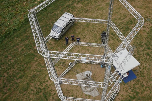
After two years of dreaming, designing, and doing, [Andrey Rudenko] has finally finished 3D printing his concrete castle. We’re sure a few readers will race to the comments to criticize the use of “castle” as an acceptable descriptor, but they’d be missing the point. It’s been only three months since he was testing the thing out in his garage, and now there’s a beautiful, freestanding structure in his yard, custom-printed.

There are no action shots of the printer setup as it lays down fat beads of concrete, only close-ups of the nozzle, but the castle was printed on-site outdoors. It wasn’t, however, printed in one piece. [Andrey] churned out the turrets separately and attached them later. He won’t be doing that again, though, because moving them in place was quite the burden. On his webpage, [Andrey] shares some insight in a wrap-up of the construction process. After much experimentation, he settled on a layer height of 10mm with a 30mm width for best results. He also discovered that he could print much more than his original estimation of 50cm of vertical height a day (fearing the lower layers would buckle).

With the castle a success, [Andrey] plans to expand his website to include a “posting wall for new ideas and findings.” We’re not sure whether that statement suggests that he would provide open-source access to everything or just feature updates of his future projects.

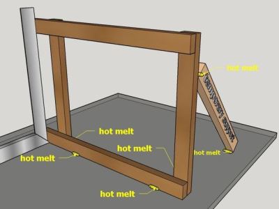
Wooden supports for concrete bridging.
[Andrey] used wooden supports to print concrete bridges.
We hope the former. You can check out its current format as the Architecture Forum, where he explains some of the construction capabilities and tricks used to build the castle.

His next project, a full-scale livable structure, will attempt to print 24/7 (weather permitting) rather than the stop-start routine used for the castle, which turned out to be the culprit behind imperfections in the print. He’ll have to hurry, though. [Andrey] lives in Minnesota, and the climate will soon cause construction to take a 6-month hiatus until warm weather returns. Be sure to check out his website for more photos and a retrospective on the castle project, as well as contact information—[Andrey] is reaching out to interested parties with the appropriate skills (and investors) who may want to help with the new project.

[via 3ders.org]

[Thanks Brian]

THP Semifinalist: Retro Populator, A Pick And Place Retrofit For A 3D Printer

A huge theme of The Hackaday Prize entries is making assembly of electronics projects easier. This has come in the form of soldering robots, and of course pick and place machines. One of the best we’ve seen is the Retro Populator, a project by [Eric], [Charles], [Adam], and [Rob], members of the Toronto Hacklab. It’s a machine that places electronic components on a PCB with the help of a 3D printer

The Retro Populator consists of two major parts: the toolhead consists of a needle and vacuum pump for picking up those tiny surface mount parts. This is attaches to a quick mount bolted right to the extruder of a 3D printer. The fixture board attaches to the bed of a 3D printer and includes tape rails, cam locks, and locking arms for holding parts and boards down firmly.

The current version of the Retro Populator, with its acrylic base and vacuum pen, is starting to work well. The future plans include tape feeders, a ‘position confirm’ ability, and eventually part rotation. It’s a very cool device, and the ability to produce a few dozen prototypes in an hour would be a boon for hackerspaces the world over.

You can check out a few videos of the Retro Populator below.


SpaceWrencherThe project featured in this post is a semifinalist in The Hackaday Prize. 

Continue reading “THP Semifinalist: Retro Populator, A Pick And Place Retrofit For A 3D Printer”

THP Semifinalist: Theta Printer

thetaThe early 3D printers of the 80s and 90s started off as cartesian bots, and this is what the RepRap project took a cue from for the earliest open source 3D printer designs. A bit later, the delta bot came on the scene, but this was merely a different way to move a toolhead around build plate. We haven’t really seen a true polar coordinate 3D printer, except for [Tyler Anderson]’s incredible Theta printer.

[Tyler]’s theta printer is designed to print in as many different materials as possible, without the reduction in build volume that comes with multiple toolheads on more traditional printers. It will be able to lay down different colors of plastic in a huge build volume, and even some of the weirder filaments out there, all in a single print.

The theta printer is based on a polar coordinate system, meaning instead of moving a hot end around in the X and Y axes, the build plate rotates in a circle, and the extruders move along the radius of the circle. This spinning, polar coordinate printer is the best way we’ve seen to put multiple extruders on a printer, and has the added bonus of being a great platform for a 3D scanner as well.

With four extruders, four motors to control the position of each extruder, a rotation motor, and the Z axis (that’s 10 steppers if you’re counting), this is very likely the greatest number of motors ever put in a 3D printer. Most electronics boards don’t support that many stepper drivers, and the one that will won’t be ready for the end of The Hackaday Prize. Right now, [Tyler] is running a fairly standard RAMPS board, running two extruders and R axes in parallel. Still, it’s good enough for a proof of concept.

One interesting aspect of [Tyler]’s design is something even he might not have realized yet: with a single bed and four extruders, he’s effectively made a 3D printer geared for high-volume production; simply by printing the same part with all the extruders, he’s able to quadruple the output of a 3D printer with the same floor space as a normal one. This may not sound like much, but when you realize Lulzbot has a bot farm producing all their parts, the Theta printer starts to look like a very, very good idea.

Videos of [Tyler]’s Theta below.


SpaceWrencherThe project featured in this post is a semifinalist in The Hackaday Prize.

Continue reading “THP Semifinalist: Theta Printer”

THP Entry: A Holonomic Drive 3D Printer

holo

[Sugapes] always wanted to cut a few corners and build a really, really cheap 3D printer, but the idea of using linear actuators – pricing them, sourcing them, and the inevitable problems associated with them – scared him away. One day, he realized that moving in a plane in the X and Y dimensions wasn’t hard at all; cars and robots do this every day. Instead of moving a 3D printer bed around with rods and pulleys, [Sugapes] is moving his 3D printer around with wheelsIt’s different, it’s interesting, and it’s the perfect project to show of his creativity for The Hackaday Prize.

The drive system [Sugapes] is using is called a holonomic drive system. In his build, three omnidirectional wheels are attached to continuous rotation servos, each of them mounted 120 degrees apart. The print bed is simply placed on these wheels, and with the right control algorithms, [Sugapes] can move the bed in the X and Y axes. With an extruder on a Z axis above the bed, this setup becomes a 3D printer with a theoretically unlimited XY build axis. Pretty clever, huh?

There are a few problems [Sugapes] will have to overcome to turn this project into a proper printer. The omnidirectional wheels aren’t the best at transferring movement to the bed, so a quartet of USB optical computer mice are being used for a closed loop system. [Sugapes] put up a video of his project, you can check that out below.


SpaceWrencherThe project featured in this post is an entry in The Hackaday Prize. Build something awesome and win a trip to space or hundreds of other prizes.

Continue reading “THP Entry: A Holonomic Drive 3D Printer”

Milling Curved Objects With A G-Code Ripper

HaD Mouse

Milling and routing flat surfaces is pretty much the point of a CNC router, but how about curved surfaces? Auto leveling of hobby CNC machines and 3D printers is becoming commonplace, but Scorch Works is doing just the opposite: using a probe touch probe on a CNC machine to transform a G-Code file into something that can be milled on a curved surface.

The technique is pretty much the complete opposite of Autoleveller, the tool of choice for milling and routing objects that aren’t completely flat or perpendicular to the bed with a MACH3 or LinuxCNC machine. In this case, a touch probe attached to the router scans a curved part, applies bilinear interpolation to a G-Code file, and then starts machining.

The probe can be used on just about anything – in the videos below, you can see a perfect engraving in a block of plastic that’s about 30 degrees off perpendicular to the bed, letters carved in a baseball bat, and a guaranteed way to get your project featured on Hackaday.

Continue reading “Milling Curved Objects With A G-Code Ripper”

Clay 3D Printer Keeps It Simple

Clay 3D Printer

Artist [Jonathan] has built a 3D printer specifically for printing in clay. The part count is kept to a minimum and the printer was designed to be made with basic tools and beginner skills. The intent was to not require access to a plastic 3D printer in order to build this printer. Although this build’s goal was clay printing, the extruder could certainly be swapped out for a typical plastic printer version.

This Delta uses quite a bit of MDF. The top and bottom plates are MDF, as are the bearing carriages and extruder mount plate. 12mm rods are solely responsible for the support between the top and bottoms plates as well providing a surface for the LM12UU linear bearings. These bearings are zip tied to the MDF bearing carriages. The 6 arms that support the extruder mount plate are made from aluminum tubing and Traxxas RC car rod-ends. NEMA17 motors and GT2 belts and pulleys are the method used to move the machine around.

Getting the clay to dispense was a tricky task. Parts scavenged from a pneumatic dispensing gun was used. If you are unfamiliar with this type of tool, think: Power Caulk Gun. Clay is fed into the re-fillable syringes and an air compressor provides the 30 psi required to force the clay out of the nozzle. The pressure alone controls the rate of clay flow so it is a little finicky to get the extrusion rate correct. Depending on the size of the final sculpture, 1 to 2mm diameter nozzles could be used. For larger work, 1mm layer height works well. For the smaller pieces, 0.5mm is the preferred layer height.

Continue reading “Clay 3D Printer Keeps It Simple”