A 4-bit Computer From Discrete Transistors

Anyone reading this uses computers, and a few very cool people have built their own computer out of chips, [zaphod] is doing something even cooler over on hackaday.io: he’s building a computer from discrete transistors.

Building a computer from individual components without chips isn’t something new – Minecraft players who aren’t into cheaty command blocks do it all the time, and there have been a few real-life builds that have rocked our socks. [zaphod] is following in this hallowed tradition by building a four-bit computer, complete with CPU, RAM, and ROM from transistors, diodes, resistors, wire, and a lot of solder.

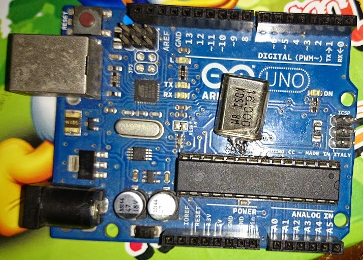
The ROM for the computer is just a bunch of 16 DIP switches and 128 diodes, giving this computer 128 bits of storage. the RAM for this project is a bit of a hack – it’s an Arduino, but that’s only because [zaphod] doesn’t want to solder 640 transistors just yet. This setup does have its advantages, though: the entire contents of memory can be dumped to a computer through a serial monitor. The ALU is a 4-bit ripple-carry adder/subtractor, with plans for a comparison unit that will be responsible for JMP.

The project hasn’t been without its problems – the first design of the demux for the ROM access logic resulted in a jungle of wires, gates, and connections that [zaphod] couldn’t get a usable signal out of because of the limited gate fan-out of his gates. After looking at the problem, [zaphod] decided to look at how real demuxes were constructed, and eventually hit upon the correct way of doing things – inverters and ANDs.

It’s a beautiful project, and something that [zaphod] has been working for months on. He’s getting close to complete, if you don’t count soldering up the RAM, and already has a crude Larson scanner worked out.

Doing Unsafe Things With A Laser Watch

[Pierce Brosnan]-era James Bond had a beautiful Omega wristwatch. Of course as with any Bond gadget, it couldn’t just tell time; it needed to do something else. This watch had a laser, and [Patrick] figured he could replicate this build.

This is apretty normal 1.5W laser diode build, stuffed into a wrist-mountable device that will kill balloons. This is really a watch, though: press a button and this thing will tell time.

In the video below, [Patrick] goes over what damage this watch can do. He manages to pop some black balloons, burn holes in a CD case, light a few matches, cut cellotape, and put tiny burn marks in his wall. The battery won’t last long – just a few minutes – but more than enough to propel [Patrick] into Youtube stardom.

There are no plans or tutorials for the build, but the teardown [Patrick] shows is pretty impressive. To stuff a laser diode, battery, and clock into a watch-sized compartment, [Patrick] needed to turn down the metal buttons to fit everything into his watch case.

Because the comments for this post will invariable fill up with concern trolls, we’re just going to say, yes, this is incredibly unsafe, no one should ever do this, and it probably kills puppies.


Serial Surgery Saves Wacom Tablet From Landfill

Years ago, [Greg] got a Wacom Artpad II graphics tablet through Freecycle. What’s the catch, you ask? The stylus was long gone. When he found out how expensive a direct replacement would be, the tablet was laid to rest in his spare parts box. Fast forward a few years to the era of the phone-tablet hybrid and [Greg]’s subsequent realization that some of them use Wacom stylii. Eight bucks later, he’s in business, except that the tablet is serial. Wacom no longer supports serial tablets, so he had to convert it to USB.

With the help of the WaxBee project and a Teensy 2.0, he would be able to emulate an Intuous2 tablet by sniffing and re-encoding the packets.  Things got a little hairy when he went under the hood to remove the ADM202 TTL-to-RS232 chip with a Dremel—he accidentally gouged some of the pads it sat on as well as a few of the traces. Feeling frustrated, [Greg] took some high-res pictures of the board and posted them to a message board. As it turns out, those pictures helped him recreate the traces and get the tablet running. A little big of glue and tape later, he was in business. [Greg] even gave himself access to reprogram the Teensy.

Solving Arduino’s Stk500_getsync() Error

[psgarcha] took a year-old Arduino Uno on an international trip and upon returning found something was wrong. Every time he would try to upload, he would get the dreaded avrdude error, ‘stk500_getsync(): not in sync resp=0x00’. The Rx light would blink a few times during the attempted upload, but the tx light did not. Somehow, something was terribly wrong with the ‘duino, and [psgarcha] dug deep to figure out why.

To test the quality of the Arduino’s serial connection, [psgarcha] performed a loopback test; basically a wire plugged into the Tx and Rx pins of the Arduino. Sending a short message through the serial port showed the problem wasn’t the USB cable, the ATmega16u2 on the ‘duino, or any traces on the board. This would require more thought.

The main reason for the error would then be no communication between the computer and the ‘duino, the wrong COM port selected, the wrong board selected in the Arduino text editor, or timing errors or a corrupt bootloader. The first three errors were now out of the question, leaving timing errors and a corrupt bootloader. Troubleshooting then moved on to ordering a new programmer, and still this didn’t work with the broken Uno.

Frustrated with one of the greatest failures to become an Arduino tinkerer, [psgarcha] took a good, long look at the Uno board. He glanced over to an Arduino Mega board. Something looked different. On the Uno, the resonator had blown off. Problem found, at least.

Replacing the blown part with a hilariously large can crystal oscillator, [psgarcha] was back in business. This isn’t how you would fix 99% of getsync() errors, and it’s difficult imagining a situation where a this part would randomly blow, but if you’re ever looking at a nearly intractable problem, you need to start looking at what really shouldn’t fail.

Resonator my fix (1)

Awesome rework, though.


Cloning A Board From Pictures On The Internet

[Andrew] was a pretty cool guy in the early 90s with an awesome keyboard synth that did wavetable synthesis, sampling, a sequencer, and an effects processor. This was a strange era for storage; a reasonable amount of Flash memory was unheard of, and floppy disks ruled the land. [Andrew]’s synth, though, had the option to connect SCSI drives. Like all optional add ons for high-end equipment, the current price for the Ensoniq SCSI card is astronomical and [Andrew] figured he could build one of these cards himself.

Poking around eBay, [Andrew] found the card in question – just a few passives, some connectors, a voltage regulator, and an odd chip from AMD. This chip was a 33C93A, a SCSI controller, and a trip down the Chinese vendor rabbit hole netted him one for $7. Can’t do better than that.

With the datasheet for the chip in hand and a few reasonable assumptions on how the circuit worked, [Andrew] tried to figure draw the schematic. After doing that, he found another hobbyist that had attempted the same project a few years earlier. All the nets were identical, and all that was left to do was sending a board off to the fab.

A quick trip to Front Panel Express got [Andrew] a mounting bracket for the card, and after plugging it in to the synth revealed a new option – SCSI. It worked, and with an ancient SCSI CD-ROM drive, he had boatloads of offline storage for his synth. Great work, and something we’d love to see more of.


Five Dollar RF Controlled Light Sockets

This is tens of thousands of dollars worth of market research I’m about to spill, so buckle up. I have a spreadsheet filled with hundreds of projects and products that are solutions to ‘home automation’ according to their creators. The only common theme? Relays. Home automation is just Internet connected relays tied to mains. You’re welcome.

[Todd] over at Fabricate.io found an interesting home automation appliance on Amazon; a four-pack of remote control light sockets for $20, or what we would call a microcontroller, an RF receiver, and a relay. These lamp sockets are remote-controlled, but each package is limited to four channels. Terrible if you’re trying to outfit a home, but a wonderful exploration into the world of reverse engineering.

After cracking one of these sockets open, [Todd] found the usual suspects and a tiny little 8-pin DIP EEPROM. This chip stores a few thousand bits, several of which are tied to the remote control. After dumping the contents of the EEPROM from the entire four-pack of light sockets, [Todd] noticed only one specific value changed. Obviously, this was the channel tied to the remote. No CRC or ‘nothin. It doesn’t get easier than this.

With the new-found knowledge of what each lamp socket was looking for, [Todd] set out to clone the transmitter. Tearing this device apart, he found a chip with HS1527 stamped on it. A quick Googling revealed this to be an encoder transmitter, with the datasheet showing an output format of a 20-bit code and four data bits. This was a four-channel transmitter, right? That’s where you put each channel. The 20-bit code was interesting but not surprising; you don’t want one remote being able to turn of every other 4-pack of lamp sockets.

With all the relevant documentation, [Todd] set out to do the obvious thing – an Arduino transmitter. This was simply an Arduino and a transmitter in the right frequency, loaded up with bit of carefully crafted code. [Todd] also figured out how to expand his setup to more than four lamp sockets – by changing the 20-bit code, he could make his Arduino pretend to be more than one transmitter.

With Arduino-controlled lamp sockets, the world is [Todd]’s oyster. He can add Ethernet, WiFi, Bluetooth LE, and whatever trendy web front end he wants to have a perfect home automation setup. It’s actually a pretty impressive build with some great documentation, and is probably the cheapest way to add Arduino/Internet-enabled relays we’ve ever seen.


Creating A Scanning Monochromator

If you need a specific wavelength of light for research purposes, the naïve way of obtaining that is a white source light, a prism, and a small slit that will move across your own personal Dark Side of the Moon album cover. This is actually a terrible idea; not only won’t you have a reference of exactly what wavelength of light you’re letting through the optical slit, the prism itself will absorb more of one wavelength of light than others.

The solution is a monochromator, a device that performs the same feat of research without all the drawbacks. [Shahriar] got his hands on an old manual monochromator and decided to turn it into a device that performs automatic scans.

The key of a monochromator is a diffraction grating, a mirrored surface with many fine parallel grooves arranged in a step pattern. Because of the surface of the diffraction grating, it’s possible to separate light according to its spectrum much like a prism. Unlike a prism, it’s effectively a first surface mirror meaning all wavelengths of light are reflected more or less equally.

By adding a stepper motor to the dial of his monochromator, [Shahriar] was able to automatically scan across the entire range of the device. Inside the monochromator is a photomultiplier tube that samples the incoming light and turns it into a voltage. By sampling this voltage and plotting it with MATLAB, [Shahriar] was able to plot the intensity of every wavelength of light within the range of the device. It’s all expertly explained in the video below.

Continue reading “Creating A Scanning Monochromator”